
Key Points
In this part, we will discuss:
-
Screening
-
Evaluation and planning
-
Perioperative and follow-up radiographs
Abstract
Radiographic examination is a central part of implant treatment from the planning phase to the long-term evaluation of treatment success.
Main
Standard dental radiographs allow the clinician to make an initial assessment of the bone levels available for implant treatment, but as 2-dimensional images they give no indication of bone width. In combination with clinical examination they may provide enough information to plan treatment without resorting to more complex imaging techniques. Tomographic examinations can give cross-sectional and 3-dimensional images. In addition to providing information about bone quantity they also provide some indication of the bone quality available, notably the thickness of the cortices as well as an approximation of the density of the cancellous bone.
A standard classification of bone quantity and quality has been devised and is useful to describe the degree of alveolar resorption present (fig. 1), although the quality is often a subjective assessment and is more easily classified when surgery is performed. Radiographs are also used during treatment and provide an assessment of osseointegration and long-term maintenance.

Redrawn from Lekholm U, Zarb G. Patient selection and preparation in Tissue Integrated Prostheses. Branemark P I, Zarb G A, Albrektsson T (eds). pp199–210. Quintessence, 1985. (a) Ridge resorption in the maxilla and mandible. The ridge shortly after tooth extraction is described as morphology A through progressive degrees of resorption to grossly atrophic E
Screening
A screening radiograph should give the clinician an indication of:
-
The overall status of teeth and supporting bone
-
Those sites where it is possible to place implants using a straight-forward protocol
-
Those sites where it is unlikely that implants can be placed without using complex procedures such as grafting
-
Those sites where it is inadvisable to recommend implants
-
Anatomical anomalies or pathological lesions.
In most instances the Dental Panoramic Tomograph (DPT) is the radiograph of choice (fig. 2). They provide an image within a pre-defined focal trough of both upper and lower jaws and as such give a reasonable approximation of bone height, the position of the inferior dental neurovascular bundle, the size and position of the maxillary antra and any pathological conditions which may be present. They are therefore an ideal view for initial treatment planning and for providing patient information as they present the image in a way that many patients are able to understand. These are narrow beam rotational tomographs which use two or more centres of rotation to produce an image of the dental arches. Some areas may not be imaged particularly well, but this can be minimised by ensuring that the patient is positioned correctly in the machine and that the appropriate programme is selected. The radiation dosage of a DPT is approximately 0.007 to 0.014 mSv which is less than a full mouth series of periapical radiographs where each periapical accounts for about 0.001 to 0.008 mSv. They provide more information about associated anatomical structures than periapical radiographs but with less fine detail of the teeth. It should be remembered that all DPT's are magnified images [at around ×1.3]. Distortion also occurs in the antero-posterior dimension reducing their usefulness when planning implant spacing and numbers.

This initial screening radiograph suggests that there is sufficient bone height above the inferior dental canal in the lower right jaw and below the maxillary sinuses. More detailed information of this patient is presented in results of a CT scan in figure 5
The information provided by a DPT can usefully be supplemented using other standard extra-oral and intraoral radiographs. For example, the lateral cephalogram can give more detail of the morphology of both jaws close to the midline, and this can be useful when planning overdenture treatment (fig. 3). Standard occlusal views may also aid in assessing the bone morphology in the lower jaw. Should further information be required following the screening examination, then the appropriate tomographic examination is made.

There is extensive resorption in the maxilla (Class E). The mandible is treatable with implants and the maxilla would require extensive grafting
Radiography for single tooth replacement or small bridges in individuals with little bone loss can normally be accomplished by intra-oral radiographs taken with a long cone paralleling technique. However it must be remembered that an overall evaluation of the mouth should be made for a full assessment of treatment needs. Image quality is of the utmost importance and it should be ensured that all relevant anatomical structures are shown on the image being used and that any allowances for distortion of the image are made. This is particularly important when assessing available bone height above the inferior dental canal and when working close to other important anatomical structures.
Computerised digital radiovisiography is becoming more commonplace and can provide an alternative medium to produce an image. As the detectors are solid state the doses used can be greatly reduced. Additionally, manipulation of the digitally derived image may provide further information about relative bone densities, particularly when assessing peri-implant bone density changes by subtraction radiography. It is likely that their application in implant dentistry will become more widespread.
Evaluation and planning
Radiographic stents
Evaluation and planning
-
Radiographic stents
-
Computerised tomography
-
Scan Ora
In order to optimise the information provided by more advanced radiographic techniques, it is necessary to provide information about the planned final restoration. A stent which mimics the desired tooth setup is constructed and radiographic markers usually made of gutta percha or another radio-opaque material placed within it (fig. 4a). Alternatively, if the patient has a suitable acrylic denture, radiographic markers may be placed within occlusal or palatal cavities cut in the acrylic teeth. The denture can also be replicated in clear acrylic to provide the radiographic stent. The radiopaque marker or rod can be placed in the position and angulation of the planned prosthetic set-up. Thus for a screw retained prosthesis the marker would indicate the access hole for the screw retaining the restoration. Alternatively the relation of the bone ridge to the proposed tooth set-up can be shown by painting the labial surface of the stent with a radiopaque varnish (fig. 4b). The choice of radiographic marker is important in that it should be visible on the radiographic image but not interfere with the scan. When using Computerised Tomography (CT), metal markers should be avoided as they can produce scattering on the image (see later). Stents are particularly useful in the edentulous patient as they also serve to stabilise the position of the jaws while the radiographs are being taken. When using CT for edentulous patients this is most desirable because of the long exposure time. The stent can also provide the radiographer with a true occlusal plane from which to orientate the axial scans.

This stent is a blowdown plastic with radioopaque markers at the sites of planned implant placement, to guide the radiographer to the areas of interest for sectional tomography

This allows an estimation of the position and angulation of the implant in relation to the prosthesis by the clinicians planning the restoration and the surgery
Simpler types of stent involve placing radiopaque markers eg ball bearings of various diameters or twisted wire shapes into a baseplate and are designed to help determine mesiodistal location.
Computerised tomography (CT scan)
CT scans provide the clinician with the most detailed images currently available, but given their cost and high radiation dose their use is often limited to more complex cases such as full arch maxillary reconstructions, bilateral posterior mandible imaging or to assess whether patients require extensive grafting procedures (fig. 5). CT uses x-rays to produce sectional images as in conventional tomography. High resolution images are achieved by initially scanning in an axial plane keeping the sections thin and by making the scans contiguous or overlapping. The large number of sections in a high resolution scan of a jaw approximates to a radiation dose of 3 mSv. New generation helical CT scanners are faster and have significantly lower radiation dose. The scans should be limited to the area of interest and avoid radiosensitive tissues such as the eyes. In place of conventional film the radiation is detected by highly sensitive crystal or gas detectors which is then converted to digital data. This data can then be stored and manipulated by computer software to produce a grey-scale image. The software then allows multiplane sections to be reconstituted, the quality of which are dependent on the original scan section thickness and integers between successive sections.

This shows a 3-dimensional reconstruction of the mandible and a lateral scout view showing the plane of the sections parallel to the occusal plane
Images can be produced as:
-
Standard radiographic negative images on large sheets
-
Positive images on photographic paper often in book form
-
Images for viewing on a computer monitor.
Whatever the presentation format, it is of great importance to align the scan properly. The patient's head is aligned in the scanner with light markers, and a scout view obtained which gives an image similar to a lateral skull film (fig. 5a). The radiation dose of this scout view is low and can be repeated if the alignment is incorrect. Generally the mandible is scanned with slices parallel to the occlusal plane and the maxilla using the same plane or one parallel to the floor of the nose. Deviation from this alignment will result in the cross-sectional slices not being in the same direction as the proposed implant placement (See radiographic stents).
Figure 5 illustrates the reformatted images which can be produced including:
-
Sections in the same plane as the original slices (the raw data)(fig. 5b)
Figure 5b: Computerised axial tomography of the jaws of the same patient illustrated in figure 2 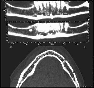
The lower part of the figure shows a horizontal section through the mandible which is in the same plane as the original scan slices. The computerised data from these slices is reformatted to produce all of the other images in figure 5. The upper part of the figure shows two slices in the same plane as a DPT but at different depths through the mandible
-
Cross-sectional images of the jaw at right angles to the original plane of slice, numbered consecutively and radially around the arch. These are the most useful images (fig. 5c and 5e)
Figure 5c: Computerised axial tomography of the jaws of the same patient illustrated in figure 2 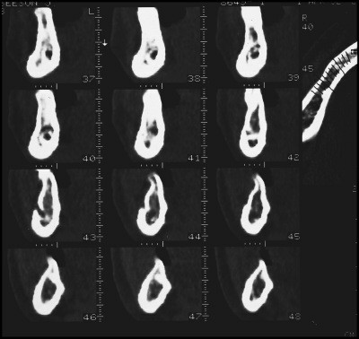
Cross sectional images of the right mandible. The location of the cross sections is shown on the horizontal section in the top right corner of the figure.The mental foramen is clearly shown in section 43 and the inferior dental canal can be traced in sections distal to this (higher numbers) and the incisive branch anteriorly. The sections give an indication of the cortical thickness and density of trabeculation within the central part of the jaw
Figure 5e: Computerised axial tomography of the jaws of the same patient illustrated in figure 2 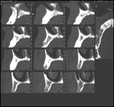
Cross-sectional images of the right maxilla from the midline (section 25 showing the incisive canal) to the premolar area. The nasal cavity is visible on most of the sections. The last section 36 shows the anterior part of the maxillary sinus (laterally) and the nasal cavity with the inferior turbinate. The location of the cross sections is shown on the horizontal section in the top right corner of the figure
-
Images in the same plane as a conventional DPT, but at different depths (fig. 5b).
-
3-dimensional reconstructions of the surface morphology of the jaw (fig. 5a and 5d).
Figure 5d: Computerised axial tomography of the jaws of the same patient illustrated in figure 2 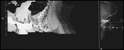
A 3-dimensional reconstruction of the right maxilla


Heavy metals will produce a scatter-like interference pattern if they are present in the slice under examination and the interference will therefore appear in all the generated sectional images. Extensive interference may render a CT scan unreadable and can be produced by large posts in root canals or heavily restored teeth where the plane of examination passes through such a tooth as well as an area of critical interest.
In some instances therefore either a compromise has to be made in the direction of scanning or a different method of examination chosen (eg scan ora, see later). Consideration should also be given to removing the offending metal prior to examination if appropriate in the overall treatment plan.
The various scan images can be measured for selection of implant length and diameter. Although the nominal magnification of the images is 1:1 some machines and cameras produce images where the magnification may vary. A scale is usually incorporated alongside the various groups of images and the real magnification can be determined from this. A correction factor can then be applied to measurements taken directly from the films.
In contrast to hard copies of the scans, one of the advantages of the computer-based image software programs (eg Simplant) is that it is possible to produce images of implants (and their restorative components) which can then be 'placed' within the CT scan. This enables the clinician to evaluate the relationships between the proposed implants and ridge morphology, anatomic features and adjacent teeth. When used in conjunction with a radiographic stent the possibilty of reproducing the orientation envisaged at the planning stage is greatly increased.
Scan Ora
Scanora is an example of a new generation of sophisticated tomographic devices most similar to conventional DPT machines, but with facilities to generate high quality sectional images (fig. 6). In contrast to CT scanning where the sectional images are software generated, the Scan Ora produces a tomographic image directly onto film. It uses complex broad beam spiral tomography and is able to scan in multiple planes. The scans are computer controlled with automatic execution but still rely heavily on good patient positioning and experience in using the machine. The patient's head is carefully aligned within the device and this position recorded with skin markers and light beams. A DPT image is produced from which the sites which require sectional tomographic data are determined (fig. 6a). The patient is repositioned in exactly the same alignment and the appropriate tomographic programme selected for the chosen region of the jaw.

The high quality DPT image is produced at a magnification of x1.7. This shows a patient with failure of development of multiple permanent teeth in the maxilla
The Scan Ora magnification is ×1.3 or ×1.7 for routine DPTs but is ×1.7 for all sectional images. Tomographic sections are normally 2 mm or 4 mm in thickness (figs 6b and 6c). As with all tomograms the image produced includes adjacent structures which are not within the focal trough which therefore appear blurred and out of focus. Because the scan sections are thicker and fewer the overall patient dose is much less than a CT scan. The amount of detailed information provided is considerably less than a CT scan but is usually sufficient for all but the most complex cases.

This shows a cross-sectional image of the maxillary ridge in the same individual. The height and width determinations must take account of the magnification

A Scan Ora section through the anterior mandible of the patient whose DPT is shown in figure 2b. The cross section shows a retained deciduous incisor and a very thin bone profile apical to this. The thickness improves at the chin
In order to facilitate planning using images at different magnifications, transparent overlays depicting implants of various lengths and diameters at the corresponding magnifications can be superimposed directly on the radiograph. These provide a simple method of assessing implant sites and implant placement at different angulations.
Perioperative and follow-up radiographs
Intra-oral radiographs may be useful at the time of implant placement allowing visualisation of drills or direction indicators and their relation to adjacent teeth or anatomical structures. Radiovisiography is useful as it produces an instant image at a lower radiation dose. At second stage surgery radiographs may be required to ensure full seating of abutments when direct visualisation has not been possible at the time of surgery (See Part 4).
During the prosthetic phase it is essential to ensure full seating of components and frameworks (fig. 7). This may not be possible by direct vision because of the soft tissues, and radiographs provide the only method of checking fit. It is essential that radiographs are taken at 90° to the long axis of the implant under examination and it is therefore recommended to use long cone parallel radiographs. Only a relatively small deviation from the correct angulation may make the radiograph unreadable. Correct angulation is easy to check when using threaded implants as the thread profile is clearly seen when the x-ray is taken at 90°(fig. 7).

Th implant thread profiles are clearly visible which indicates that the film was taken with a good paralleling technique. This enables the clinician to check that the abutments are correctly seated on the implants, the framework fits the abutments and that the bone levels at this stage are close to the top of the implant
Baseline radiographs to show crestal bone levels and the state of the peri-implant bone should be taken as part of normal documentation at the time of fitting the final prosthesis. These should be repeated on an annual basis for the first 2 or 3 years to establish that the bone levels are stable. It should be remembered that some initial bone loss will occur during the first year of function with some implants but that a steady state should then be established thereafter. The interval between radiographs may be extended if the bone appears stable over the first few years of function (See Part 10).
Many of the problems which arise during treatment or once the prosthesis is in function are most readily diagnosed using standard intra-oral views (figs 8 and 9), these include:
-
Burnt bone syndrome
-
Bone loss
-
Component loosening
-
Screw breakage
-
Implant fracture
-
Adjacent endodontic lesions
-
Loss of integration.

The top figure show the edentulous ridge and a non-restorable premolar. The middle figure shows healing abutments connected to the three implants following stage 2 surgery and the lower figure shows the completed case. The parallel projection geometry is very similar in all three radiographs which allows comparisons and the ability to check the fit of the component parts

An adhesive bridge provides the provisional restoration. The patient experienced discomfort and the radiograph shows an apical radiolucency around the implant. Bone resorption has occurred because of damage to the bone at implant placement. This is caused by failure to cool the bone during the drilling operation and is referred to as burnt bone syndrome
These conditions will be dealt with more fully in Part 10, Complications and Maintenance.
Conclusion
Radiographs play an important part in the successful planning and execution of implant treatment. It is important to have an understanding of the different techniques available and their appropriate application. They are an important part of the patients records and as such constitute a significant proportion of the medico-legal documentation of the patient. It is the responsibility of the clinician to ensure that radiographs are appropriate, readable and are retained and repeated at accepted intervals throughout treatment and follow-up.

Redrawn from Lekholm U, Zarb G. Patient selection and preparation in Tissue Integrated Prostheses. Branemark P I, Zarb G A, Albrektsson T (eds). pp199–210. Quintessence, 1985. (b) Bone quality is on a four point scale: Type 1 is mainly cortical, Type 2 is a dense cortex and cancellous space, Type 3 is a thinner cortex and less dense cancellous bone, Type 4 has a very thin cortex and sparse bone trabeculae in the medullary space

(A) classification of anterior mandible (anterior to mental foramen) (B) classification of posterior mandible (posterior to mental foramen) (C) classification of anterior maxilla (D) classification of posterior maxilla. Reproduced by kind permission of Munksgaard International Publishers Ltd, Copenhagen, Denmark. From Cawood J I, Howell R A, Int J Oral and Maxillofac Surg 1991; 20: 75

It clearly shows very little bone height in the right maxillary edentulous region. This area is only treatable following extensive bone grafting. The only significant bone mass in the upper jaw is in the premaxilla

A lateral skull view demonstrates the ridge profile of both upper and lower jaws in the midline
Author information
Authors and Affiliations
Rights and permissions
About this article
Cite this article
Floyd, P., Palmer, P. & Palmer, R. Radiographic technique. Br Dent J 187, 359–365 (1999). https://doi.org/10.1038/sj.bdj.4800280
Published:
Issue Date:
DOI: https://doi.org/10.1038/sj.bdj.4800280
