
Abstract
A fundamental understanding of the theory and measurement procedures for characterizing a solenoid is crucial for making a project cost-effective and achieving the desired performance for its use in a LINAC. This paper attempts to comprehend the beam dynamics of charged particles by considering the conservation of canonical angular momentum, which can take on positive, negative, and zero values. The analytical expression to generate a parallel beam using a solenoid is derived. The effect of the final beam size on the values of a solenoid’s spherical aberration coefficient and the position of the minimum beam size with respect to the focal length is studied using electron trajectories. A practical procedure to tune the above two parameters of a solenoid is demonstrated by simply modifying the demountable disks connected at each end. A mathematical model is proposed to accurately determine the axis of a solenoid and the magnetic centre using the measured magnetic field data, which is validated experimentally. Several solenoids, used in the 9.5 MeV 10 kW electron LINAC suitable for sterilizing medical products and food irradiation, have been characterised using this procedure.
Introduction
Solenoids are widely used in applications ranging from undergraduate laboratory apparatus to high-tech sophisticated instruments like accelerators, electron microscopes and MRI. Several textbooks are available for the design and beam dynamics of solenoids1,2,3,4,5. Solenoids are commonly used for focusing low energy charged particles beams. Comparative studies of the focusing properties between the solenoid and quadrupole magnets are discussed in the literature6. However, FANL used a superconducting solenoid for focusing proton LINAC up to an energy of 100 MeV7. Apart from particle accelerators, superconducting solenoids are also used for MRI magnets8,9. For the SINBAD facility at DESY solenoids for beam focusing were employed, and the limit of their misalignment was studied. Beam experiences additional kick due to the mis-alignment of a solenoid, causing emittance growth. Therefore, alignment of the solenoid within 100 µm is demanded for the project10. Solenoids are also used in high power gun for RF sources11. The Axisymmetric magnetic field produced by a solenoid increases the electron beam transport by confining the beam and making it harder for its suitable application in microwave amplification. Focusing of charged particles beams by solenoids depends on various beam parameters like emittance growth due to spherical aberrations and non-linear space charge forces12. Solenoids are also used to improve the imaging performance of time-resolved electron microscopes13, as well as in particle therapy, radiographic diagnostics machines, and for rare isotope beams production14. An analytical expression for charged particle dynamics in a solenoid is derived using the conservation of canonical angular momentum5,15. All such calculations consider rotational symmetry of the magnetic field. Therefore, the alignment of the solenoid plays a significant role in achieving the desired performances16,17,18.
We have developed 9.5 MeV 10 kW electron LINACs in which large number of solenoids have been used. Despite having a large volume of literature, several factors still need to be discovered about the beam dynamics and characterization of the solenoids. This has motivated us to address these issues in this paper. We describe a viable solution with validated results using the experimental data and simulation results. To enhance the project's cost-effectiveness and ensure timely execution, a comprehensive understanding of the theory and the proper analysis of the experimental data are essential. The paper addresses issues related to two types of solenoids: (i) air core coil and (ii) coil surrounded by an iron jacket.
The following topics are discussed:
-
1.
The derivation of the beam dynamics of charged particles by considering the conservation of canonical angular momentum with non-zero values involve a more detailed analysis of the particle motion than typically presented in available literatures5,15 that often assume only zero canonical angular momentum.
-
2.
Comparison of the field quality of air core and coil surrounded by iron jacket solenoids.
-
3.
The derivation of an approximate analytical formula to find the central field of a solenoid with an iron jacket.
-
4.
Utilizing a solenoid for the generation of parallel beams.
-
5.
The procedure involves tuning the values of the spherical aberration coefficient and focal length of a solenoid, both of which significantly impact its optical properties. This is achieved by modifying the demountable disks connected at each end.
-
6.
Determination of the magnetic axis and centre of a solenoid from the measured magnetic field data.
Some of the results are verified using single particle trajectory using Opera Simulation Software19. The self-Field produced by the beam is ignored in the calculation.
The axis of a solenoid can be determined by means of the single stretched wire method20. Electrical voltage is induced across a wire when its ends move in the opposite direction with respect to the centre of the solenoid. The induced voltage is at a minimum when the wire coincides with the solenoid axis. However, it is important to note that this method provides an integrated measurement and is not suitable for detecting the error field profile of a solenoid. The accuracy is lower because the transverse field intercepts only near the edges of the solenoid.
The magnetic axis of a solenoid was determined by moving two sets of induction coils along the longitudinal direction inside the solenoid21. Induced voltage was measured on the fly, and the flux density was expressed as a Taylor series. The magnetic axis was identified by detecting the minimum of the local field gradient. However, a limitation of this procedure is the need for a 2.5 m travel range of the linear movement system to characterize a 0.390 m long solenoid21. Additionally, achieving an accuracy of 50 µm requires multiple runs (e.g., 6 runs) per direction for averaging. Furthermore, the minimum of the local gradient is not sharp, as observed in the measured data, and the field calculated by this method is averaged over the area of the search coil. Therefore, this method does not provide a point measurement.
In contrast to the previous method, we propose a new procedure for axis determination using a 3D Hall sensor with a magnetic field sensitive volume of (0.1 × 0.01 × 0.1) mm3 and a magnetic field accuracy of 100 PPM, which are readily available in the market. A linear travel range exceeding the length of the solenoid by 10% is sufficient for accurate axis determination. The zero-crossing method is employed for this purpose, and periodic calibration of the Hall sensor is conducted using an NMR probe. Magnetic field data is acquired at a 1.0 k-sample/s sampling rate for rapid averaging of measured field data. These features render the proposed method accurate to better than 50 µm, robust, and fast. Additionally, this process minimizes error transverse fields of the solenoid, which cause emittance growth, to within 1 G. The measurement of error fields enables the estimation of mechanical inaccuracies present in the solenoid, providing opportunities for further improvement.
Solenoids play a crucial role in halo removal for intense high-energy beams in storage rings and colliders22. Projects such as the Hollow Electron Lens23,24 and Electron Cooler25 require the precise alignment of solenoids within 50 µm. Our proposed measurement method fulfills this stringent requirement.
Beam dynamics in a magnet having rotational symmetry like solenoid
Consider a particle of charge q and momentum, P is moving in Z direction through a solenoid. Z is the symmetric axis of the solenoid. The momentum P can be expressed as \(\overrightarrow {P} = \overrightarrow {P}_{Z} + \overrightarrow {P}_{ \bot }\). Assume that \(\overrightarrow {P}_{Z} \gg \overrightarrow {P}_{ \bot }\). Magnetic field in a solenoid has rotational symmetry. Therefore, the canonical angular momentum is conserved. The magnetic field of a solenoid can be expressed as4,21,26
where Bz0(Z) = on-axis field and \(\hat{r}\) and \(\hat{z}\) are the unit vector along r and Z direction, respectively.
In this paper we will consider the linear term only.
Canonical angular momentum
where A is vector potential.
Equation (2) can have three possible solutions depending on the value of the constant is
-
1.
Positive
-
2.
Negative
-
3.
Zero
The possible solutions are examined below.
Magnetic field, \(\overrightarrow {B}_{Z}\) of a solenoid can have vector potential
We know that the trajectory of a charge particle q with an average momentum in Z direction inside a solenoid, is a helix. We have solved this under impulsive approximation5,15, which means the particle experiences azimuthal kick only when it passes through the fringe field regions of the solenoid. Therefore,
Let the distance of the centre of the helix from the magnetic axis be \(R_{d}\). The radius of the helix,\(R_{h}\) can be obtained from the force equation
From Eqs. (2), (3) and (5) we have
- Case 1::
-
For \(R_{d} > R_{h}\),\(\ell_{Z}\) is positive. Hence, the trajectory does not include the magnet axis as shown in Fig. 1.
Figure 1 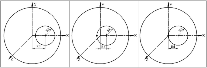
Case 1: In this case the trajectory does not include the magnet axis, O (\(R_{d} > R_{h}\)). Case 2: In this case the trajectory includes the magnet axis, O (\(R_{d} < R_{h}\)). Case 3: In this case the trajectory passes through the magnet axis, O (\(R_{d} = R_{h}\)).
- Case 2::
-
For \(R_{d} < R_{h}\),\(\ell_{Z}\) is negative. Hence, the trajectory includes the magnet axis as shown in Fig. 1.
- Case 3::
-
For \(R_{d} = R_{h}\), \(\ell_{Z}\) is zero. Hence, the trajectory passes through the magnet axis as shown in Fig. 1. In this case when the particle is launched at a distance \(2R_{h}\) from the centre of the magnetic axis, then the radius of the helix will be \(R_{h}\), as documented in the literature \(\left( {R_{h} = \frac{R}{2}} \right)\)15.

Graphical representation of Eq. (6) is shown in Fig. 1 for all the three cases.
Particle trajectory of a 9 MeV electron through a 0.384 m long solenoid with a peak magnetic field of 0.1192 T is shown in Fig. 2. The actual trajectory shows a very similar nature to that predicted by Eq. (6). Case 1 and case 2 are closer to practical scenarios because the beam always has finite emittance. Self-field produced by the beam is ignored in the calculation.

X–Y projection of the trajectory of a 9 MeV electron through a solenoid with a peak magnetic field of 0.1192T. Electron is projected off-axis with a small angle with Z-axis to have a small momentum in the perpendicular direction for both case 1 and case 2.
Use of solenoid to generate parallel beam and focusing
A particle of charge q and momentum P is launched at a small angle \(\alpha_{1}\) with respect to the Z axis from a point (0, y1, − Z1) that reaches at the solenoid entrance at P1(α1Z1, y1,0) with momentum (Pin, 0, P) where Pin = P \(\alpha_{1}\). The axis of the solenoid is in the Z direction with \(B = B_{Z} \hat{Z}\) extending from Z = 0 to L.
At the entrance of the solenoid, the fringe field provides an azimuthal kick to the charge particle, which is represented by \(\vec{P}_{\theta 1} = - \frac{{qBR_{in} }}{2}\). Therefore,
From the triangle ΔOP1P2,
Because of the azimuthal kick at the entry of the solenoid, the particle rotates by an azimuthal angle \(\theta_{h}\) as it traverses along the length of a solenoid of length L.
We have by using Eqs. (7) and (8)
Just before exit of the solenoid the particle will have both radial \(\left( {P_{out} } \right)\) and azimuthal \(\left( {P_{\theta 2} } \right)\) momentum that can be expressed as
From triangle ΔOAhP2, we have \(R_{out} = 2R_{h} \cos \theta_{2}\).
However, at the exit, the fringe field will provide a kick in the azimuthal direction, incrementing the azimuthal momentum by an amount \(\frac{{qBR_{out} }}{2}\). Therefore, the resultant azimuthal momentum will be zero, which will make the canonical momentum zero.
So, after exiting the solenoid, the particle will have transverse momentum only in the radial direction. This will guide the charge particle towards the solenoid axis. Assume that at a distance \(Z_{2}\) from the end of the solenoid, the particle will cross the solenoid axis, making an angle \(\alpha_{2}\) with the Z axis.
If the particle is launched on the axis and at the entry of the solenoid, then \(Z_{1} = 0 \, and \, R_{in} = 0.\)
In that case, we get from Fig. 3, \(\theta_{1} = \pi /2\) and hence \(\theta_{2} = \frac{qBL}{{2P}} - \frac{\pi }{2}\).

Projection of trajectory on X–Y plane at the centre of the solenoid of length L(Z). O and Ah are the axis of the solenoid and helical trajectory, respectively. Particles enter at point P1(Rin, θ1,0) and exit of the solenoid at P2 (Rout, − θ2, L).
Equation (13) can be written as
If \(\tan \left( {\frac{qBL}{{2P}}} \right) = \infty {\text{ then }}Z_{2} \to \infty\), This is the condition of generating parallel beam.
So, \(\frac{qBL}{{2P}} = (2n + 1)\frac{\pi }{2}\) where n is integer 1, 2, 3 …..etc.
If a particle of momentum P and charge q is launched on the axis inside a solenoid which satisfies the Eq. (15), then a parallel beam will come out of the solenoid.
From Fig. 3, we have
Using Eqs. (10) and (16) we get \(\tan \theta_{2} = \tan \left( {\frac{qBL}{{2P}} - \tan^{ - 1} \frac{2P}{{qBZ_{1} }}} \right)\).
Using Eq. (13)
If \(Z_{1} \to \infty\) then
For small lens approximation
If an electron with momentum P is launched on the axis inside the solenoid, at an angle, θ, with the solenoid axis and the field integral satisfies Eq. (15), then the electron will emerge parallel to the axis. For example, if the solenoid extends from − 0.2 to 0.2 m and has a field integral \(\int\limits_{ - 0.15}^{\infty } {B_{Z} dZ} = 0.04499{\text{ Tm}}\) then the trajectory of an electron with an energy of 4.3262 MeV will become parallel to the solenoid axis. Similarly, by varying the injection point, electrons with different energies can be made parallel.
Estimation of the spot size on the focal plane
Several factors control the beam size at the focal plane. However, major contributions come from (i) Beam emittance, (ii) Chromatic aberration due to the energy spread of the beam, and (iii) Spherical aberration arising from the field profile of the solenoid. The radius of the final beam \(\left( {R_{f} } \right)\) can be correlated with the initial beam \(\left( {R_{0} } \right)\) through the relation4
where \(\varepsilon = {\text{ emittance}}, \, \frac{\Delta \gamma }{\gamma } = {\text{ energy spread and }}C_{s} {\text{ = spherical aberation coefficient}}{.}\)
However, in this article, we will only consider the effect of \(C_{s}\)4, which depends on the field profile of the solenoid by studying the single-particle trajectory. The motion of a charged particle inside a solenoid is coupled motion. The solenoid rotates and focus the beam, as explained in Eqs. (10) and (18). The angle of rotation depends on \(\int {B_{Z} dZ}\) which is governed only by the total current, NI and not on the geometrical parameters of the solenoid. This can be obtained using Amper’s law, which is also observed in simulation and measurement. We have considered three cases (i) a coil of length, inner, and outer radii are 384 mm, 83 mm and 210 mm, respectively, (ii) the inner radius of the coil is increased by 1.5 times to 124.5 mm, and (iii) the coil used in case (i) is put inside a 12 mm thick iron jacket. The total length, inner and outer radii of the solenoid with iron jacket are 418 mm, 30 mm and 225 mm, respectively. In all three cases, the total current in the solenoid is kept as 45,800 Amp. turn. \(\int {B_{Z} dZ}\) for all three cases is found to be 0.05753 Tm. Peak magnetic fields are 0.119251 T, 0.107529 T, and 0.146073 T, respectively. Field profiles for the three different cases are shown in Fig. 4. The value of \(C_{s}\)(1/m2) for the three different cases are 8.23, 6.44 and 35.84, respectively.

Field profile for three different cases for the same NI but different geometrical parameters of solenoids that produce same \(\int {B_{Z} dZ}\).
It is clear from Fig. 4 that iron jacket increases the peak field but reduces the fringe field region and increases \(C_{s}\). In any accelerator, components are placed close to each other, and fringe fields cause interference between various components, which may not be desirable in most cases. Several magnetic elements are used in our 9.5 MeV 10 kW electron LINAC. We have experimentally observed the undesirable effect of fringe fields. Therefore, there shall be a trade-off between controlling the field span and the value of \(C_{s}\) for a practical machine.
Field profile of a solenoid without iron can be calculated analytically. Peak field with iron jacket can be estimated using the relation \(B = \frac{{\mu_{0} NI}}{gap} = \frac{{4\pi 10^{ - 7} \times 45800}}{0.394} = 0.146076T\), which is close to the simulated (and measured) value.
The theoretical prediction as given in Eq. (20) demands lower value of \(C_{s}\) for better focusing. But how low, that needs to be estimated. We have done single particle trajectory to find the effect of \(C_{s}\) on the final beam size. Particles at six different points on an ellipse are launched along the Z direction. 3-D trajectory and its projection on the transverse planes are shown in Fig. 5. Initial beam size along X is ± 40 mm and final sizes are ± 1.35 mm and ± 4.08 mm at 0.359 mm and 0.390mm, respectively. Therefore, it is clear that the beam size is nearly 3 times smaller at 0.359 m compared to the size at the focal plane for large beam size. It is important that the target be placed prior to the focal plane in order to obtain the minimum beam size.

3-D trajectory of elliptical beam through a solenoid of focal length 0.39 m and its projection on the transverse planes. Initial beam size along X is ± 40 mm and final sizes are ± 1.35 mm and ± 4.08 mm at 0.359 mm and 0.390 mm, respectively (A). Trajectory is zoomed to show the size of the beam at focal point (B).
Now, we consider two entirely different solenoids but having similar \(C_{s}\) value as given in Table1.
Field profile of the two different solenoids, Sol-1 and Sol-2 is presented in Fig. 6. Important parameters of the two different solenoids are also shown in Table 1. An electron located at four different points of a 12.5 mm radius circle is launched one by one along the Z direction and its trajectories are shown in Fig. 7. According to the theory, the final beam size will be 0.188 mm at the focal plane. The focal distance, as calculated using Eq. (18) is around 0.419m, where the beam size is slightly larger than the theoretical prediction. However, the minimum beam size is considerably smaller at 0.40m which is 0.025mm, as observed in Fig. 7. Therefore, it is possible to reduce the beam size from 12.5 mm to 0.025 mm. Even in the case of such a high value of \(C_{s}\), it is possible to reduce the beam size by nearly 500 times. However, the other parameters will affect the final beam size, as explained in Eq. (20). Therefore, there is no point in demanding a very low value of \(C_{s}\) unless it is required. This kind of beam size reduction is acceptable for most LINACs including ours.

Field profile of the two different solenoids, Sol-1 (D100mm) and Sol-2 (D50mm) having similar \(C_{s}\) value.

Trajectory of the particle through Sol-1 (D100mm). Rectangular area surrounded by dotted line represents the edges of the solenoid (A). Trajectory is zoomed to show the size of the focus beam (B).
However, in case of Sol-2, degradation of beam quality is observed, where the ratio of the inner radius of the solenoid to the radius of the input beam \(\left( {\frac{{R_{iSol} }}{{R_{0} }}} \right)\) is 2. Whereas, the ratio is 4 for Sol-1. Trajectory of the electron is shown in Fig. 8 for Sol-2.

Trajectory of the particle through Sol-2 (D50mm). Rectangular dotted line represents the edges of the solenoid (A). Trajectory is zoomed to show the size of the focus beam at minimum beam position (B).
In the case of Sol-2, despite having a similar \(C_{s}\) value, the minimum beam size is around 0.2 mm. Therefore, not only the value \(C_{s}\) plays a significant role, but the ratio \(\left( {\frac{{R_{iSol} }}{{R_{0} }}} \right)\) also influences the reducing of bean size. Consequently, in most LINAC machines, the inner radius of the solenoid is kept large compared to the beam radius.
We have already shown that \(\int {B_{Z} dZ}\) will depend only on the total current of the solenoid. However, various other important parameters of a solenoid such as \(C_{s}\), focal length, and peak magnetic field, can be altered as needed by varying the inner radius of the iron jacket while keeping NI constant. As we decrease the inner radius, the peak central field and \(C_{s}\) will increase, but the fringe field zone will reduce. At the same time, the focal length reduces, i.e., the focusing power increases. Therefore, based on the requirement of the project, several properties of a solenoid can be tuned by varying the inner radius of the iron jacket. A de-mountable disk at both the ends are provided on the iron jacket to make the solenoid versatile. Several such magnets are built, characterised, and used in various applications. Figure 9 shows the variation of spherical aberration coefficient and focal length for 10 MeV electrons with the radius of the inner iron jacket.

Variation of spherical aberration coefficient and focal length for 10 MeV electron with the radius of the inner iron jacket.
Find the axis of a solenoid using measured magnetic field data
Axially symmetric magnetic fields produced by a solenoid are utilized in numerous applications. Therefore, it is crucial to determine the axis of a solenoid to achieve the desired performance. Mathematical modeling and measurement procedures are described with practical examples. The field at the centre of an ideal solenoid is produced only along axial direction, BZ. Both the transverse field, BX and BY are zero on the axis (0, 0, Z), as shown in Fig. 10. An integrated 3-axis Hall sensor is essential to detect this condition. On the Y = 0 plane, BY is zero, and BX linearly varies with X, crossing 0 at the centre. For a given Z, BX(−X) = −BX(X) on the Y = 0 plane. BX is maximum at the edges of the magnet; therefore, experiments are conducted at the edges to achieve better accuracy. The above properties are used to detect the centre of the solenoid using simulated and experimental data.

Frame of reference of 3D sensor positioning bench (X, Y, Z) and mis-aligned solenoid (X′, Y′, Z′).
A 3-axis sensor positioning bench (PB) and a 3-axis SENIS Hall sensor attached to a 3MH5C tesla meter are used for field measurement. The magnetic field sensitive volume of the sensor is approximately (0.1 × 0.01 × 0.1) mm3, and its angular accuracy is ± 0.5°. To align the Hall sensor horizontally (in the X–Y plane), the sensor is moved inside an aligned dipole magnet as part of the initial alignment procedure. The solenoid is placed on the magnet alignment bench, which has a circular base. Both the PB (X,Y,Z) and the Hall sensor are positioned horizontally. BY is adjusted to zero at both ends from (− 0.03, 0, L/2) to (0.03, 0, L/2) M1 line and from (− 0.03, 0, − L/2) to (0.03, 0, − L/2) M2 line by using the alignment table. Here, L is the length of the solenoid. This alignment procedure is used to define the X–Y plane.
Suppose the solenoid is tilted by an angle θ about Y axis with respect to the reference frame of PB about the point O. The frame of reference of the mis-aligned solenoid is defined as X′Y′Z′ (Fig. 10). The field BZ along the Z axis is measured. \(\frac{{\partial B_{Z} }}{\partial Z}{\text{ vs}}{. }Z\) changes sign at Z = 0. This plot defines the magnetic centre along the length. Any lateral shift along the length is adjusted based on the measurement.
The following two matrices are used to convert the position and field from the PB frame (X, Y, Z) to the solenoid frame (X′, Y′, Z′).
If \(P_{1}^{\prime} (X_{1}^{\prime} ,Y_{1}^{\prime} ,Z_{1}^{\prime} )\) is the new centre of the solenoid then \(B_{X1}^{\prime} = B_{Y1}^{\prime} = 0.\)
To find the value of \(\theta\), a curve is drawn between \(B_{X1}^{\prime} {\text{ and }}\theta\) using data given in Table 2 and shown in Fig. 11. The dimensions of the solenoid considered for the present study are as follows: Length, inner diameter and outer diameter are 0.4, 0.187, and 0.305 m, respectively. \(B_{X1}^{\prime}\) is zero for angle 5 degree as obtained from Fig. 11. As we are detecting zero crossing, closer data points are not needed.

Variation \(B_{X1}^{\prime} (T)\) with angle in degree.
For \(\theta\) = 5 degree, the point (− 0.03, 0, 0.2) in the PB frame will transform to (− 0.012, 0, 0.202) in the solenoid frame, and the corresponding field \(\left( {B_{X1}^{\prime} ,B_{Y1}^{\prime} ,B_{Z1}^{\prime} } \right)\) will be (− 8.154E−03, 0, 6.259E−02). Similarly, the point (0.03, 0, 0.2) will transform to (0.047, 0, 0.197) and corresponding field \(\left( {B_{X1}^{\prime} ,B_{Y1}^{\prime} ,B_{Z1}^{\prime} } \right)\) will be (8.154E−03, 0, 6.259E−02). Similarly, for the point (0, ± 0.03, 0.2), the corresponding field \(\left( {B_{X1}^{\prime} ,B_{Y1}^{\prime} ,B_{Z1}^{\prime} } \right)\) will be (0, ± 8.154E−03, 6.259E−02). Therefore, the field is symmetric but opposite in sign, as in case of an ideal solenoid. The axis of the solenoid can, therefore, be determined efficiently and accurately by measuring magnetic field at a few points in the PB frame. Now, the reference frame of the PB is tilted by 5 degrees to match with the solenoid frame, and the simulated values of the fields are plotted in Fig. 12.

Variation of BX (BY) and derivative \(\left( {\frac{{\partial B_{Z} }}{\partial Z}} \right)\) along the solenoid axis for different X(Y) as obtained from simulation after transforming the PB frame to the solenoid frame. This is exactly the same as expected from an ideal solenoid.
However, in any practical magnet, this ideal nature may not be observed due to the presence of various unavoidable geometrical errors. Figure 13 illustrates the field variation of BX and BY along the axis. For X = Y = 0, BX and BY vary within ± 1 G rather than zero, as in case of an ideal solenoid. However, this error is very small and within an acceptable limit.

(A) Measured magnetic field data of BX and BY, and the derivative of the axial field along the axis of the solenoid. Field profiles are very close to the ideal solenoids as expected. Only at X = Y = 0, BX and BY varies with Z within ± 1G rather than zero as in case of ideal solenoid (B).
An efficient determination of accurate magnetic axis is not possible without using an integrated 3-axis sensor. A set of horizontal and vertical steering coils is placed inside each solenoid for beam steering, for use when required. This correction coils are capable of generating a 180 G-cm integrated field in each direction27,28. The derivative of the axial field is also observed to cross zero, as predicted by the theory. In our earlier machines, air core solenoids using OFHC Cu are used, but now proposed to use Al-strip solenoid with iron jacket because of several advantages and reduced cost. The benefits of using Al-strip solenoid with an iron jacket over OFHC-Cu are summarized in Table 3.
Conclusions
We have conducted a thorough examination of charged particle dynamics within a solenoid, utilizing the conservation of canonical angular momentum, which can take on positive, negative, and zero values. The solutions have been rigorously justified through particle trajectories. Additionally, the analytical expression for the focal length of a solenoid is derived, along with the condition necessary to generate a parallel beam using a solenoid. The theoretical predictions have been verified through particle trajectories. Our findings reveals that the rotation angle of the charged particles inside a solenoid is solely depended on the \(\int {B_{Z} \partial Z}\) that depends on the product of current in each turn and numbers of turns. It is independent of the geometrical parameters of the solenoid. Furthermore, we have introduced and experimentally demonstrated a method to tune the spherical aberration coefficient and the focal length of a solenoid by varying the inner diameter of the demountable iron disk connected at both ends. Particle trajectory observations indicate that not only the value of \(C_{s}\), but also the ratio of inner radius of the solenoid to the radius of the beam, plays a significant role in reducing the beam size.
We have also proposed and experimentally demonstrated an efficient approach for accurately determining the axis and the magnetic centre of a solenoid, leveraging a 3-axis Hall sensor and probe positioning bench. This procedure has been instrumental in characterizing several solenoids for various applications, including 10 kW 9.5 MeV LINACs28. The accurate determination of the axis of a solenoid is crucial for optimizing the performance of charged particle dynamics, considering the axisymmetric magnetic field in all calculations.
Through this methodology, we have successfully designed, characterized, and utilized several solenoids for various projects. We have developed two types of solenoids (i) LCW cooled air core OFHC Cu and (ii) Anodized Al-strip with iron jacket employing indirect cooling with ordinary water. Pros and cons of the two different types of solenoids are presented. We proposed based on our analysis that Al-strip solenoids with iron jacket is cost effective and well-suited for a 9.5 MeV 10 kW LINAC project.
Data availability
The datasets used and/or analyzed during the current study available from the corresponding author on reasonable request.
References
Bruce Montgomery, D. Solenoid Magnet Design (Wiley-Interscience, 1969).
Clarke, N. Solenoid Design and Construction (Noside Limited, 2003).
Reiser, M. Theory and Designed of Charged Particle Beams (Wiley-VCH, Verlag GmbH & Co., 2008).
El-Kareh, A. B. & El-Kareh, J. C. Electron Beams, Lenses and Optics (Academic Press, 1970).
Busch, H. Berechnung der bahn von kathodenstrahlen im axialsymmetrischen electro magnetischenfelde. Z. Phys. 8, 974–993. https://doi.org/10.1002/andp.19263862507 (1926).
Hofmann, I. Performance of solenoids versus quadrupoles in focusing and energy selection of laser accelerated protons. Phys. Rev. ST Accel. Beams https://doi.org/10.1103/PhysRevSTAB.16.041302 (2013).
Di Marco, E. J., Khabiboulline, E., Orris, D. F., Tartaglia, M. A. & Terechkine, I. Superconducting solenoid lens for a high energy part of a proton linac front end. IEEE Trans. Appl. Supercond. 23, 4100905 (2013).
Sinha, G., Sundararaman, R. & Singh, G. Design concepts of optimized MRI magnet. IEEE Trans. Magn. 44(10), 2351 (2008).
Oraon, A., Oraon, R., Ghosh, S., Aich, S. & Sinha, G. Simulation-based design of optimized symmetric MRI magnet modified with ferromagnetic shell. IEEE Trans. Magn. 56(2), 8000207 (2020).
Yamin, S., Assmann, R., Marchetti, B. & Zhu, J. Beam dynamics studies for beam focusing and solenoid alignment at SINBAD, IPAC2018, Vancouver, BC, Canada, 4026 https://doi.org/10.18429/JACoW-IPAC2018-THPMF001.
Iqbal, M. et al. Design, simulation and analysis of beam optics and solenoid of high-power gun for RF power source. Nucl. Inst. Methods Phys. Res. A 1014, 165703 (2021).
Batygin, Y. K. Dynamics of intense particle beam in axial-symmetric magnetic field. Nucl. Inst. Methods Phys. Res. A Accel. Spectrom. Detect. Assoc. Equip. 772, 93–102 (2015).
Denham, P. & Musumeci, P. Space charge aberrations in single shot time-resolved transmission electron microscopy. Phys. Rev. Appl. 15, 024050. https://doi.org/10.1103/PhysRevApplied.15.024050 (2021).
Tamayose, L. E., Zamora, J. C., Fortino, G. F. & Flechas, D. Simulation of the RIBRAS facility with GEANT4. Braz. J. Phys. 52(3), 89 (2022).
Kumar, V. Understanding the focusing of charged particle beams in a solenoid magnetic field. Am. J. Phys. 77, 737–741. https://doi.org/10.1119/1.3129242 (2009).
Arpaia, P. et al. Measuring the magnetic axis alignment during solenoids working. Sci. Rep. 8, 11426. https://doi.org/10.1038/s41598-018-29667-1 (2018).
Baumgärtel, C., Smith, R. T. & Maher, S. Accurately predicting electron beam deflections in fringing fields of a solenoid. Sci. Rep. 10, 10903. https://doi.org/10.1038/s41598-020-67596-0 (2020).
Yang, Z. et al. Analysis of the influence of a solenoid magnetic field in the azimuth transmission system. Sci. Rep. 11, 16242. https://doi.org/10.1038/s41598-021-95783-0 (2021).
Opera, https://www.3ds.com/products-services/simulia/products/opera/.
DiMarco, J. et al. Solenoid magnet alignment at Fermilab. In Proceedings of 16th International Magnetic Measurement Workshop (IMMW) (2009).
Petrone, C., Sorti, S., Dalane, E., Mehl, B. & Russenschuck, S. Induction-coil measurement system for normal and superconducting solenoids. IEEE Trans. Appl. Supercond. 32(6), 9000605 (2022).
Stancari, G. et al. Collimation with hollow electron beams. Phys. Rev. Lett. 107, 084802 (2011).
Stancari, G. et al. Conceptual design of hollow electron lenses for beam halo control in the large hadron collider, Geneva, Switzerland, Tech. Rep. FERMILAB-TM-2572-APC, CERN-ACC-2014-0248 (CERN, 2014).
Perini, D., Kolhemainen, A., Rossi, A., Sadovich, S. & Stancari, G. Design of high-performance guns for the HL-LHC HEL. J. Instrum. 16, T03010 (2021).
Von Freeden, L. AD E-Cooler PRR, Magnetic System, https://indico.cern.ch/event/1157504/contributions/4860640/attachments/2445816/4192831/20220517_ppr_slides.pdf.
Montgomery, D. B. Solenoid Magnet Design, The Magnetic and Mechanical Aspects of Resistive and Superconducting System (Wiley-Interscience, Wiley, 1969).
Sinha, G. et al. Design and characterisation of anodised aluminium strip solenoids. In PAC 2023, ID 484, March 13–16 (2023).
Sandha R. S. et al. Development, testing and qualification of 9.5 MeV, 10 kW food irradiation. In Linac, NAARRI International Conference-NICSTAR-2023, LBICC, Kochi, Kerala, India, 9–12 (2023).
Acknowledgements
The authors acknowledge K Sreeramulu for technical discussion and fabrication of the solenoids, B Srinivasan for assistance during field measurements, and Navin Awale for help in manuscript preparation. Thanks to Amitabh Das for valuable comments and suggestions on the draft. The authors are also indebted to Dr. S.V. Nakhe, T A Puntambekar, and Jishnu Dwivedi for their encouragement.
Author information
Authors and Affiliations
Contributions
GS: Conceptualized the problem, performed the mathematical calculations, defined all the procedures, and wrote the manuscript. RM: Magnetic field measurement.
Corresponding author
Ethics declarations
Competing interests
The authors declare no competing interests.
Additional information
Publisher's note
Springer Nature remains neutral with regard to jurisdictional claims in published maps and institutional affiliations.
Rights and permissions
Open Access This article is licensed under a Creative Commons Attribution 4.0 International License, which permits use, sharing, adaptation, distribution and reproduction in any medium or format, as long as you give appropriate credit to the original author(s) and the source, provide a link to the Creative Commons licence, and indicate if changes were made. The images or other third party material in this article are included in the article's Creative Commons licence, unless indicated otherwise in a credit line to the material. If material is not included in the article's Creative Commons licence and your intended use is not permitted by statutory regulation or exceeds the permitted use, you will need to obtain permission directly from the copyright holder. To view a copy of this licence, visit http://creativecommons.org/licenses/by/4.0/.
About this article

Cite this article
Sinha, G., Malik, R. Dynamics of charged particles in a solenoid and the accurate determination of the magnetic axis of a solenoid using measured field data. Sci Rep 14, 9778 (2024). https://doi.org/10.1038/s41598-024-58645-z
Received:
Accepted:
Published:
DOI: https://doi.org/10.1038/s41598-024-58645-z
Comments
By submitting a comment you agree to abide by our Terms and Community Guidelines. If you find something abusive or that does not comply with our terms or guidelines please flag it as inappropriate.
