
Abstract
We have produced the world’s first 700 nm, ultra-fine polyester nanofiber via continuous research and development using state-of-the-art nanotechnology. The proposed sea/island composite-spinning technology has improved the quality of conventional mass-produced nanofibers. Sea/island composite spinning produces high-strength polyester nanofibers using conjugated (two components) spinning theory. The separation of sea–island components is based on the different degrees of polymer dissolution in alkali solution; specifically, resolution sea polymer (modified polyester) has dissolution rates that are 1000 times faster than that of island polymer (polyester). The resulting nanofibers have a large surface area, high absorption, and good distribution and filtration effects, which are suitable for a variety of applications, including functional sportswear, inner wear, skin-care products, filters, precision grinding cloths, and so on.
Introduction
Within the synthetic fiber industry, a number of value-added products have been developed based on differentiation technology, including textiles and high tenacity, sense of touch and color tone materials. Nonetheless, owing to the strong cost competitiveness and improvement in the technologies used in developing countries such as those employed in South East Asia, deindustrialization (or the hollowing out of industries) has occurred in Japan, especially within the fiber industry. Therefore, the Japanese fiber industry must produce innovative fiber materials and develop functional applications based on precision-conjugated melt-spinning technology. Essentially, the fiber industry must develop finer and stronger fiber materials. In this regard, the expectations of new functionality and the opening of new markets as a result of novel nanotechnologies are high.
As fiber manufacturing technology has progressed from micro-order to nano-order and new functions in various fields have been rapidly developed, we have produced commercial polyester nanofibers with unprecedented uniform diameters and high tenacity. When the functionality of nano-size materials is used in actual products, new applications can be identified, and the functions of existing products can be dramatically improved. Thus, we expect new markets to open up for nanofiber materials.
Purpose of development
There are four main categories related to the manufacturing of fine fibers (Table 1):
-
i)
Non-woven technologies, in which molten polymer is blown to produce fine-fiber sheets.
-
ii)
Polymer blend technologies, in which two types of polymers are melt-blended and spun into a random sea/island structure and the sea component is removed by dissolution.
-
iii)
Electro-spinning methods, in which polymer dissolved in solvent is removed through micro-orifices at certain voltages to produce non-woven sheets.
-
iv)
Sea/island cross-section-conjugated spinning technologies, in which the melt of one polymer is extruded as the sea and the melt of another polymer is extruded as islands into the spinneret. Subsequently, the sea and island components are combined and spun through the spinneret, and the sea component is removed by dissolution.
As shown in the table, current fine-fiber manufacturing methods present several disadvantages. For instance, the fibers often present diameters on the order of micrometers ((i) and (iv)), the tensile strength is relatively low ((i)–(iv)), most of the products made from these technologies are non-woven sheets ((i)–(iii)) and organic solvent is often employed, which must be recovered. In addition, the productivity of the procedures is relatively low (iii).
To overcome the aforementioned problems, we aimed to develop fibers with the following characteristics: (i) superior physical properties, (ii) uniform fiber diameter and (iii) a filament yarn-type structure. Moreover, (iv) the material must be manufactured by a commercially applicable process.
Outline of the development
Thus, we have succeeded in developing commercially available, high-tenacity polyester nanofibers characterized by a filament form, a tenacity that is two times greater than that of conventional microfibers, and a uniform fiber diameter of 300–700 nm. Moreover, we developed various functional products based on these nanofibers (Table 2).
To produce high-tenacity polyester nanofibers with fine diameters, ∼1000 island components were used in the proposed sea/island-conjugated melt-spinning procedure. Compared with conventional technologies, which have several tens of island components, a large number of islands were used in the proposed procedure.
High-tenacity nanofibers were obtained by controlling the birefringence of polymers used in conjugated melt-spinning technology. Fine fibers have more highly oriented crystallization (high birefringence) and lower residual elongation owing to the cooling effect in the spinning line. As a result, to obtain high-tenacity material, fine fibers cannot be drawn at high draw ratios. We solved various problems attributed to the birefringence of fine fibers and found that appropriate polymer combinations used in conjugated melt spinning have low birefringence.
The sea polymer possesses an alkaline hydrolysis rate that is ∼1000 times faster than that of the island polymer. As a result, the island components can be separated by treatment with aqueous solution, and organic solvents are not required.
Results and Discussion
Characteristics of the technology
The results of this technology can be summarized as follows:
1. Polymer design and precision-conjugated melt-spinning technology
We developed unique polymer designs and sea/island-type precision-conjugated melt-spinning technology. The cross-section of the fiber, which includes ∼1000 islands with a thin layer (<50 nm) of sea polymer, is shown in Figure 1. High productivity in the manufacturing process (cost-competitive) was achieved because less sea components had to be removed, which led to a higher production speed.

Cross-section and separation process between sea and islands. A full color version of this figure is available at Polymer Journal online.
Several simulations were performed to estimate the dissolving speed of the sea polymer via alkaline hydrolysis. The configuration of island and sea components in the simulation was surmised as follows: 300 islands with a diameter of 500 nm were present in the conjugated cross-section and were located in 10 pitch circles. Moreover, the weight ratio of sea to islands varied from 30 to 70%. We simulated the ratio of the dissolution rate of sea to island components by assuming that the sea components completely dissolved by alkaline hydrolysis and that the island components were insoluble in alkaline solution. As the result, to minimize island dissolution and the dispersion of island diameters, the ratio of the dissolution rate of the sea component to the island component must be greater than 1000 (Table 3). The sea polymer was a modified polyester produced from hydrophilic monomer and dissolved ∼1000 times faster via hydrolysis.
2. Design of the proposed conjugated melt-spinning technology.1, 2, 3
A melt-spinning process can be simulated by the theoretical formula shown in Figure 2. The boundary conditions of the expression are as follows: (i) the polymer temperature at the end of the solidification process along the spinning line is the glass transition temperature of the polymer and (ii) the parameters in the formula of elongational viscosity are the shear viscosity and temperature. The spinning line profiles (diameter (D), deformation rate (v), temperature (T), tensile stress (F), elongational viscosity (β) and birefringence (Δn)) can be calculated.

Theoretical equation of melt spinning.
In the course of this research, a spinning simulation model of the flow of two conjugated polymers was used to estimate and design the birefringence of each polymer used in the conjugated spinning process.
Utilizing the simulation results to design the properties of the polymer, we were able to identify a specific combination of polymers as sea/islands components to suppress the birefringence of the island polymer, which was transformed into a high-strength nanofiber. The conjugated fiber can be drawn at a high draw ratio, and high-tenacity nanofibers were obtained after the sea polymer dissolved. The specific combination of polymers and the corresponding theoretical investigation are explained in the following paragraph.
In the theoretical equation, v is the speed of the spinning line (that is, the fiber speed), T is the temperature, Ta is the temperature of air, F is the tensile stress, D is the diameter of the spinning line, W is the weight of fiber from the spinnerets, ρ is the density, Cf is the air resistance stress, g is the acceleration of gravity, h is the heat conductivity coefficient, Cp is the specific heat at a constant pressure, β is the elongational viscosity and η is the shear viscosity.
The theoretical equation for conjugated spinning has been developed as described below.
First, we compared the spinning profiles of single PET and poly ethlene terephtalate (PET)/poly methyl methacrylate (PMMA) blend polymer fibers (Figure 3).

Spinning profiles of PET fibers and high-Tg PMMA/PET blend polymer fibers.
A combination of polymers with different glass transition temperatures was employed. Namely, PET (Tg=70°) and PMMA (Tg=116°) was used as the higher Tg component and the lower Tg component, respectively. The polymer blend was prepared by mix extruding the polymers, which were dried in advance.
The following features were observed during the spinning of the polymer blend:
The solidification point moved upstream (Figure 3).
The birefringence of the PET component decreased (Table 4).
To identify interactions between the two components in the polymer thinning process along the spinning line, the thinning profile, birefringence of each component, tensile strength and elongation of the spun fibers were measured in the sheath–core conjugate cross-section, as shown in Figure 4.

Conjugated spinning machine and sheath/core fiber cross-section. A full color version of this figure is available at Polymer Journal online.
To observe interactions between the two polymers, interference microscopic images of conjugated fibers produced at 5 km min−1 from sheath/core PET/high-Tg PMMA were obtained. High-Tg PMMA present in the core of the fiber was non-continuous, and breakage was observed at various positions (Figure 5a) owing to the rapid solidification of PMMA compared with PET, which remained in a thinning process in the molten state. Owing to the breakage of PMMA, two types of fiber structures were observed. One material consisted of parallel PET and PMMA fibers (part A in Figure 5b), while the other consisted of an empty (hollow) center surrounded by PET (part B in Figure 5b). When fractures occurred in the PMMA, the hollow part was slightly compressed and was thinner than the filled fiber. As shown in Figure 5c and Table 5, the birefringence of PET in part A was significantly lower, and part B showed a high birefringence that was equal to that of pure PET fibers.

Analysis of the longitudinal section of a conjugated yarn along its fiber axis: (a) TEM image, (b) observations via interference microscopy and (c) schematic depiction of birefringence.
Low birefringence and large residual elongation were obtained in blended polymers and PET and 2% PMMA subjected to sheath/core-conjugated spinning (Tables 4 and 5). In blend polymer fibers, the diameter of PMMA particles, which were stretched due to the spinning stress, was <100 nm. As a result, many surfaces were generated, indicating that the surface tension between PET and PMMA, which was generated at the polymer interface, may not affect the macroscopic properties of the material, such as the elongation and draw ratio of blended and conjugated fibers.
The proposed model of the interaction between the two conjugated polymers in the thinning process, which is related to the birefringence of each polymer, can be applied to a series or parallel model (Figure 6). The aforementioned results revealed that the suppression of birefringence was preceded in the parallel model, and a higher glass transition temperature polymer governed the spinning profile.

Deformation model of the two polymers. A full color version of this figure is available at Polymer Journal online.
Based on the parallel and series deformation model (Figure 6), the melt-spinning equation for the mono-component model mentioned above was modified into an equation for a two-component model (Table 6). As shown in Figure 7, we simulated the molecular orientation (birefringence) of the PET component in sheath/core-conjugated spinning in the parallel model. The simulated birefringence of the PET was nearly identical to the actual data obtained from the parallel model.

Spinning profile simulation: PET and PET/PMMA-conjugated spinning. A full color version of this figure is available at Polymer Journal online.
Similar to the PET/PMMA sheath/core cross-section model, the sea polymer has a higher Tg (+10–20°) than the island polymer (PET), and the birefringence of the PET component in the sea/island-conjugated fiber was low, even when fine (1–2 μm) diameters were obtained. The birefringence of the PET component in the sea/island-conjugated fiber was lower than that of PET and sea polymer fiber alone. Thus, the sea/island-conjugated fiber could be drawn at a high draw ratio, and the island part was transformed into a high-strength nanofiber after the sea was dissolved by alkaline hydrolysis (Table 7).
The mechanism of the proposed process can be discussed as follows. When sea polymer (modified polyester polymer) and PET are spun independently at the same spinning speed, sea polymer tends to solidify earlier (upstream) in the thinning process than PET. Sea polymer accelerates and reaches the spinning speed upstream from PET, and the spinning stress is enhanced owing to its high Tg. Such acceleration induces a lower spinning stress in PET compared with that of the island (the low Tg polymer), which results in low birefringence PET.
3. Product development.4, 5
Nano-order effects include surface area, adsorption, dispersion and separation effects. Utilizing the aforementioned nano-order effects, we developed new products with nano-order functions. Several examples of these products are provided below.
-
i)
Golf gloves utilizing high friction. The fine asperity on a nanofiber textile surface produces friction, which leads to anti-slip properties on the textile surface.
-
ii)
Anti-slip golf gloves are a common example of these types of materials. To improve performance during the golf swing, we collected relevant data to develop gloves that minimize rotation or slippage that may result in a missed shot. Muscle activity was measured on the four types of muscles that are activated during the swinging motion (Figure 8). The results showed that the muscle activity was lower when the nanofiber gloves were worn due to the higher friction coefficient during swinging (electromyogram) (Figure 9). Thus, the golf club can be controlled by a smaller force, which leads to a grip force-relieving effect and good swing performance. Therefore, we developed functional gloves based on the relationship between product materials and motion performance.
Figure 8 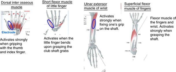
Muscles used during a golf swing. Superficial flexor muscle of the fingers. A full color version of this figure is available at Polymer Journal online.
Figure 9 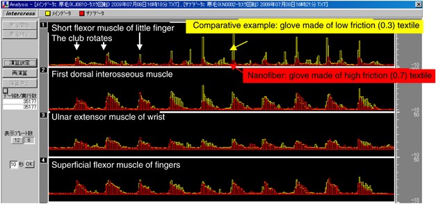
Muscle activities that occur during a golf swing and glove textiles with different friction coefficients.
-
iii)
Dispersing effect: polishing cloths (Figure 10). For base materials for memory media, polishing must be performed to obtain high compact configuration and integration. The surfaces of hard disks and semiconductors must be smoothed on the Angstrom level. We applied the proposed nanofiber textiles to the polishing process. When nanofiber clothes were used with grinding sands, the grinding sand particles were evenly dispersed over the surface gaps between nanofibers (Figure 11). In this manner, the target surface properties of base materials were formed, and a highly compact configuration was achieved.
Figure 10 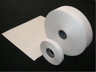
Polishing cloth and wiping goods. A full color version of this figure is available at Polymer Journal online.
Figure 11 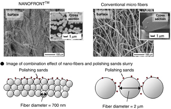
Image of the nanofiber polishing cloth and grinding sands used during polishing. A full color version of this figure is available at Polymer Journal online.
-
iv)
Separation and filtering function: filters. To control the cleanliness of clean rooms, high-functioning filters must be used. However, high-functioning filters consume large amounts of electricity because blowers must be used to compensate for high pressure losses, which are attributed to the use of dense filters with extremely small pore sizes and enabling greater trapping rates. In this respect, the development of energy-saving filters with low pressure losses (energy-saving), long service lifetimes and high trapping rates is desired.
-
v)
Currently in this field, 300-nm-diameter glass filters are often employed. To reduce the disposal load of waste filters, we propose that polyester nanofiber filters can be used as easily disposable filters (can be incinerated after use). These materials are high-functioning filters consisting of fibers with different diameters such as nanofibers, which can solve the aforementioned inconsistencies in filtering functions (Figure 12).
Figure 12 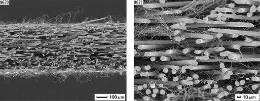
Thirty percentage blended nanofront, which achieves a low pressure (121 Pa) and high DOP trapping rate (99.99%) (dioctyl phthalate (DOP) particle size: 0.15–0.25 μm).
-
vi)
Furthermore, the proposed nanofiber filter is expected to fill the gap between filters and membranes. We are promoting the development of nanofibers as materials for various applications such as water treatment, air filtering, medical filters, and so on.


Future plan
Since the commercial production of nanofibers began in July 2008, we have promoted the development of nanofiber products, utilizing their high surface area, adsorption, dispersion and separation properties, which are attributed to nano-order effects, in textiles and various industrial applications, such as medical, electronics and filters. Using polymer technology, precise conjugated spinning procedures and textile fabrication technology (which are cost-competitive and create high-tenacity nanofibers), we will further pursue high-functional nanofiber products for practical applications.
References
Yoshimura, M., Iohara, K., Nagai, H., Takahashi., T. & Koyama, K. Fiber structure in high speed melt spinning of poly(ethylene terephthalate)/polymetylmethacrylate. Sen-i Gakkaishi 58, 287–293 (2002).
Yoshimura, M., Iohara, K., Nagai, H., Takahashi, T. & Koyama, K. Analysis of the effect of incorporation of a small amount of PMMA on fiber structure formation of PET. J. Macromol. Sci. Phys., B 42, 191–201 (2003).
Yoshimura, M., Iohara, K., Nagai, H., Takahashi, T. & Koyama, K. Structure formation of blend and sheath/core conjugated fibers in high speed spinning of PET including a small amount of PMMA. J. Macromol. Sci. Phys. B 42, 327–341 (2003).
Kamiyama, M. Development of polyester nano fiber, 44thMan-Made Fibers Congress Dornbirn, Austria 21–23 (2005).
Iimuro, H. Business development of polyester nano fiber (NanofrontTM), International Nanofiber Symposium 2009, Japan 16–18 (2009).
Author information
Authors and Affiliations
Corresponding author
Rights and permissions
About this article
Cite this article
Kamiyama, M., Soeda, T., Nagajima, S. et al. Development and application of high-strength polyester nanofibers. Polym J 44, 987–994 (2012). https://doi.org/10.1038/pj.2012.63
Received:
Revised:
Accepted:
Published:
Issue Date:
DOI: https://doi.org/10.1038/pj.2012.63
Keywords
This article is cited by
-
Effect of Polyethylene Glycol on Melt Spinning of Poly(Acrylonitrile-co-1-Vinylimidazole)
Fibers and Polymers (2022)
