
Abstract
We have demonstrated a proof-of-principle experiment of reference-frame-independent phase coding quantum key distribution (RFI-QKD) over an 80-km optical fiber. After considering the finite-key bound, we still achieve a distance of 50 km. In this scenario, the phases of the basis states are related by a slowly time-varying transformation. Furthermore, we developed and realized a new decoy state method for RFI-QKD systems with weak coherent sources to counteract the photon-number-splitting attack. With the help of a reference-frame-independent protocol and a Michelson interferometer with Faraday rotator mirrors, our system is rendered immune to the slow phase changes of the interferometer and the polarization disturbances of the channel, making the procedure very robust.
Introduction
To ensure the security of sensitive data transmission, a series of keys must be securely transmitted between distant users, referred to here as Alice and Bob. Recently, the quantum key distribution (QKD)1,2 has become useful for distributing secret keys securely. The use of QKD over fibers and free space has been demonstrated many times3,4,5. Currently, there are even commercial QKD systems available6,7,8.
In most QKD systems, a shared reference frame between Alice and Bob is required. For example, the alignment of polarization states for polarization encoding QKD or interferometric stability for phase encoding QKD plays an important role in those systems. Although alignment operations have been shown to be feasible, they do require a certain amount of time and cost to perform. As an alternative, Laing et al. proposed a reference-frame-independent (RFI) protocol9 to eliminate the requirement of alignment. This protocol uses three orthogonal bases (X, Y and Z), in which the X and Y bases are used to estimate Eve's information and the Z basis is used to obtain the raw key. The states in the Z basis, such as the time-bin eigen-states, are naturally well-aligned, whereas the states in X and Y are superpositions of the eigen-states in Z. RFI-QKD could be very useful in several scenarios, such as earth-to-satellite QKD and path-encoded chip-to-chip QKD9. However, real-life RFI-QKD systems are vulnerable to the photon-number-splitting (PNS) attack10,11,12 because a weak coherent light source is usually used instead of a single-photon source. To our knowledge, there has not yet been an experimental demonstration of RFI-QKD in a long-distance fiber, performed in a way that is secure against a PNS attack13.
However, in the RFI protocol, we must use a finite number of signals to estimate the optimal secure key rate. If Alice and Bob wait for too long, our result will be bad due to misalignment of the frames. Hence, we must consider this protocol in finite-key scenarios. A method for estimating key rate has been described in26.
In this letter, a new data analysis method for decoy states in the RFI-QKD protocol is proposed. We provide an experimental demonstration of RFI-QKD with the decoy method19. The secure key bits can be generated by our system with up to a 50-km quantum channel distance in finite-key scenarios.
Results
Theoretical analysis with decoy states
Review of the protocol
The encoding in RFI-QKD is very similar to the six states protocol14. We denote that |0〉 and |1〉 consist of the Z basis,  and
and  consist of the X basis,
  and
and  consist of the Y basis. For simplicity, we define XA(B), YA(B) and ZA(B) as Alice(Bob)'s local measurement frames for the X, Y and Z bases respectively. In a QKD experiment with well-aligned measurement frames, Alice and Bob should make sure that XA = XB = σX, YA = YB = σY, ZA = ZB = σZ, in which σX, σY and σZ are Pauli operators. However, meeting this requirement may not be easy. One can imagine that |0〉 and |1〉 are time-bin eigen-states and further assume that the quantum channel or interferometer introduces an unknown and slowly time-varying phase β between |0〉 and |1〉. This implies the following:


In each round, Alice chooses one of the encoding states and sends it to Bob through the quantum channel and Bob measures the incoming photon with XB, YB or ZB, chosen at random. After running the protocol for the appropriate number of rounds N, we can calculate the bit error rate for the ZAZB basis:

Here, β should be nearly constant during the N trials. C is used to estimate Eve's information:

In a practical QKD system, usually EZZ ≤ 15.9%, so the secret key bit rate is R = 1 − h(EZZ) − IE, where h(x) is the Shannon entropy function. Eve's information IE is given by

in which,


Decoy states method for the RFI-QKD system
The results mentioned above are based on the use of a single-photon source. Practical QKD implementations using a weak coherent light source must also use the decoy states method to overcome a PNS attack in a long-distance scenario15,16,17. However, the original decoy states method cannot be applied to the RFI system directly. Here, we discuss how to develop decoy states for RFI-QKD implementations.
Assume that Alice randomly modulates the weak coherent laser pulses with three mean photon numbers μ, ν (μ > ν) and 0, which are called signal, decoy and vacuum pulses, respectively. For every intensity, Alice and Bob perform the RFI-QKD protocol and then they obtain the counting rates Yμ, Yν and Y0 for signal pulses, decoy pulses and vacuum pulses, respectively. Alice and Bob also obtain the error rates EμZZ, Eμxy and Eνxy, (where x, y = X, Y). For example, EμXY represents the error rate of key bits generated in the case that Alice prepares signal pulses under the X basis while Bob measures the incoming states with the Y basis. According to decoy theory16, the secret key bits rate R can be calculated as follow:

Here,  is the lower bound of the counting rate of the single-photon pulses and IE is Eve's information for sifted key bits. Yμ and EμZZ are directly observed in the experiment and
  is given by the following equation20:

The next step is to calculate IE according to (6) or its upper bound. The upper bound of IE is related to  , which is defined as the lower bound of C for the single-photon pulses. The upper bound of IE also depends on the upper bound of the error rate of the key bits generated by single-photon pulses under the ZZ basis
  . According to decoy theory, the following equality applies:

The challenge is to estimate  by using Eμxy and Eνxy. For simplicity, without loss of generality, we assume that Eμxy ≥ 1/2 and Eνxy ≥ 1/2 for all x, y (if not, Bob can simply flip his bits corresponding to the relevant basis x, y). There are two ways to calculate
  :
:
-
1
Using the same method as in the original decoy states, as follows:

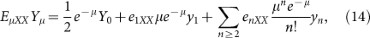
Here, enxy (x, y = X, Y) denotes the error rate for the key bits generated by n photon pulses under the x, y basis, yn represents the counting rate of n photon states. Assuming that enxy = 1(n ≥ 2), we obtain that the lower bound of e1xy

Next,
 is given by
  , where,
  ,
,  . Below, we describe the second way to calculate
  .
. -
2
We note that
and,

However, enXX and enXY are not indepdendent. We assume that Bob obtains some arbitrary two-dimensional density matrices ρ+ and ρ− after Alice prepares and sends |+〉 and |−〉, respectively, through the quantum channel. As described in Ref. 18, Alice and Bob's raw key bits are at first distributed in an unbiased fashion (if not, Alice and Bob can perform some classical randomization operations). Thus, it is not restrictive to assume that Eve symmetrizes Alice and Bob's raw key bits, because Eve does not lose any information in this step. Specifically, she can flip Alice and Bob's encoding scheme with a probability of one-half, which is represented as follows:

Note that the symmetrization step can also be applied by Alice and Bob in our security analysis. With the help of the Cauchy-Schwarz inequality, we can reformulate the equation:


 is given by
  , where,
  ,
,  . Below, we describe the second way to calculate
  .
.


Here, Im(x) represents the imaginary part of a real number x. Therefore, we obtain the following:

By adding equations (14) and (15) and applying the above inequality, we find that

In the same manner, we find that

With these equations, it is easy to show that  , where, α′ = 2(1 − a)2 and β′ = 2(1 − b)2.
Thus, the optimal lower bound of c1 is given by:

This allows us to decide how to evaluate the secure key rate R through the decoy states method: 1. With counting rates Yμ, Yν and Y0, one can obtain  by using inequality (10). 2. With
  and error rate EμZZ,
  is estimated by inequality (11). 3. With the error rates Eμxy (x, y = X, Y) and counting rates
  , Y0, we obtain
  by using inequality21. 4. We calculate the upper-bound of IE based on
  and
and  using the following equations:

in which,


5. Finally, the secure key rate R can be found using equation (9). This method is applicable to the asymptotic situation. For the finite-key case, we can see that EμZZ and Eμxy must be modified before we calculate IE.
Finite-key bound
We use the method for computing the finite-key23,24,25 RIF-QKD bound described in Ref. 26. pZ is the probability that Alice and Bob choose the Z basis. We assume that the other two bases are chosen with equal probability pX = pY = p. As shown previously (5), there are four measurements needed to estimate C, they are EμXY (x, y = X, Y). For simplicity and without loss of generality, we assume Eμxy ≥ 1/2 and Eμxy ≥ 1/2 for all x, y (if not, Bob can simply flip his bits corresponding to the relevant basis x, y).
Experimentally, each value of Eμxy is estimated using m = Np2 signals. The raw key consists of  signals. As shown previously26, under the finite-key scenario, we can correct EμZZ and Eμxy as
  and
and  , where

and max{a, b} yields the lesser value of a or b.
The key generation rate per pulse against collective attacks is given by26:

In this article, we set  . To obtain the correct IE in the finite-key case, we simply use the method described in the previous section, except that we must adopt
  ,
,  instead of EμZZ, Eμxy as the effective parameters to calculate IE according to22. Finally, the secure key rate rN,col for the finite-key case can be estimated by26.
Experimental setup and results
The phase coding method was used in our system and the experimental setup is shown in Fig. 1.

The experimental setup of the reference-frame-independent quantum key distribution system with decoy states.
Channel attenuation is 0.20 dB/km. The arm-length difference of the FMI is 2 m.
The light pulses generated by Alice's coherent light source are randomly modulated into three intensities of decoy states using an intensity modulator (IM). Then, the quantum states of photons are modulated by a Michelson interferometer with a Faraday rotator mirror (FMI) according to the coding information. Light pulses are attenuated to the single-photon level by a precisely calibrated attenuator before they enter the quantum channel. An SMF-28 single-mode fiber with an attenuation of 0.20 dB/km is used as a quantum channel between Alice and Bob. To demodulate the information, Bob needs to make measurements of the arriving photons on a randomly and independently selected basis, in which the basis definitions of X, Y and Z are the same as those for Alice. There are three possible time-bins of the photons arriving at Bob's single photon detectors (SPD) because there are two FMIs in the system. The SPDs are operating in Geige mode and their effective gating windows are precisely aligned at the second time-bin.
The FMI used in this system can self-compensate for polarization fluctuations caused by disturbances in the quantum channel27. The quantum states are randomly modulated with the coding of paths and relative phases of photons. In each arm of the FMI, a variable optical attenuator (VOA) acts as the on-off switch to restrain the path of photons and the relative phases of photons can be controlled by the phase modulator (PM) of the FMI.
In this system, the X, Y and Z bases are chosen to be  ,
,  ,
,  ,
,  and (|0〉, |1〉). The coding method for these is as follows: 1) If basis Z is chosen, only one of the two VOAs in Alice's FMI is switched on to allow photons to pass through. Specifically, the time-bin eigen-state |0〉 or |1〉 will be determined when Alice switches on the long or the short arm of her FMI, respectively. In this circumstance, Bob can generate his key as long as the detector clicks. That is the code for Alice must be 0 when Bob's code is 1 and vice versa. 2) If basis X or Y is chosen, the two arms of Alice's FMI will be switched on simultaneously and photons will pass through the two arms with equal probability. The relative phases of the photons can be values from this set: {0, π/2, π, 3π/2}. The values {0, π} correspond to the X basis and {π/2, 3π/2} correspond to the Y basis.
In Fig. 2, the variation of β is random and relatively slow. Every β corresponds to a group of QBER values: Eμxx, Eμxy, Eμyx and Eμyy. We performed counts on 10,000 groups of data and then plotted the distribution of QBER values in Figure 3. This figure reveals the random variation in β between Alice and Bob and it also shows our experimental data, measured for the case in which β is universally randomly varying.

Three orthogonal states in the phase coding methods.
(a) For the X (yellow arrows) and Y (blue arrows) bases, we use |0〉 + e(iϕ)|1〉 to express the states. |0〉 and |1〉 represent the paths that the pulses travel. |0〉 is the short arm, |1〉 is the long arm. ϕ is the phase information (b) for the Z (red arrows) basis, which is expressed as |0〉 or |1〉. β in our system is a time-varying phase between Alice and Bob.

Distribution of all QBER values in our experiment.
QBER values are distributed between 0 and 1. The count of QBER n (0 < n ≤ 1) represents the summation of values ranging from n − 0.005 to n.
Fig. 4(a) shows the key generation rate per pulse only for decoy states and compares the rates with those of Fig. 4(b) by using finite-key analysis. In finite-key analysis, being able to calculate the secret key rate by our protocol depends strongly on the number of quantum signals sent in the stationary segment. Hence, the key rate for three different stationary segments is shown in Fig. 5. In the 5-s case, the number of signals is approximately 15,000 at 0 km and because this number is small, the finite key effect is strong. Using the same experimental parameters and estimation techniques, the key generation rate of our scheme is similar to the expected value under the RIF scheme. In our experiment, EZZ was mainly derived from the dark counts of detectors(e.g. approximately 0.0035 at 0 km and 0.016 at 50 km). More detailed data are shown in Table 1 and Table 2.
 is the standard error of the mean of the secure key generation rate per pulse RD.)
Calculation (line) and measurement (symbols) of secure key generation rate per pulse with decoy states as a function of channel length.
(a) and (b) both use data collected in 50 seconds to calculate the C value. At 0 km, n ≈ m ≈ 142, 937, Eμzz ≈ 0.0035. (a) Without finite-key analysis, (b) With finite-key analysis.

Calculation (line) and measurement (symbols) of key generation rate per pulse with decoy states for three different numbers of signals.
We collected data in different stationary time segments to perform calculations with the same system frequency (from top to bottom: (a) 200 seconds, (b) 50 seconds and (c) 5 seconds).
Discussion
In summary, we have experimentally demonstrated a phase coding RFI-QKD system that uses the decoy states method. The system can generate secure key bits via an 80-km optical fiber and it can effectively resist PNS attacks. In addition, when we consider the finite-key bound, we can obtain secure key bits via a 50-km optical fiber. Our system is intrinsically stable in a slowly varying environment without active alignment and it benefits from the polarization stability of the FMI. With initiatives for practical QKD underway, we believe that this experiment is timely and that it will bring such QKD systems into practical use.
Methods
Device description and experimental setup
In this experiment, we use a homemade laser that can emit 1449.85 nm weak coherent pulses with a 700 ps pulse width and a 0.052 nm line width. The FMIs in both Alice and Bob's sites have the same arm-length difference 2 m, to ensure that the time slots of the pulses after the FMIs can be separated completely. The circulator of Bob's system cannot only be used to regulate the light path coupled to one of two SPDs, but it can also be used to resist Trojan horse attacks. The intensities of the signal, decoy and vacuum states are μ = 0.6, ν = 0.2 and 0, respectively and the pulse number ratio is 6:2:1. The single-photon avalanche detectors in our experiment are the id200 model of id Quantique. The dark count probabilities of the detectors, after-pulse probability and detection efficiency, are approximately 4 × 10⁻⁵/gate, 0.358% and 11%, respectively.
We use a personal computer (PC) to control Alice and Bob simultaneously. The entire system is synchronized at 1 MHz. The major limitation comes from the rising and falling times of the commercially available VOAs, which take approximately 250 nm to switch from maximum to minimum attenuation. The master clock of the system is generated by a PCI-6602 Data Acquisition (DAQ) card (National Instruments) at Alice's site and it is distributed to Bob through a DG535 delayer (Stanford Research Systems) for accurate synchronization. A PCI-6602 DAQ Card is used to trigger the laser and another DAQ Card USB-6353. The random numbers used to select the basis and states are generated by a software pseudo-random number generator and then transformed to a hardware control signal by a USB-6353 card. The USB-6353 card also records the single-photon detection events from the SPDs and the collected raw data are transferred to the PC for basis sifting and post processing.
References
Bennett, C. H. & Brassard, G. Quantum Cryptography: Public Key Distribution and Coin Tossing. In Proceedings of the IEEE International Conference on Computers, Systems and Signal Processing 175–179 (IEEE Press, New York, 1984).
Gisin, N., Ribordy, G., Tittle, W. & Zbinden, H. Quantum Cryptography. Rev. Mod. Phys 74, 145–195 (2002).
Sasaki, M. et al. Field test of quantum key distribution in the Tokyo QKD Network. Opt. Express. 19, 10387–10409 (2011).
Stucki, D. et al. Long-term performance of the SwissQuantum quantum key distribution network in a field environment. New. J. Phys. 13, 123001 (2011).
Peec, M. et al. The SECOQC quantum key distribution network in Vienna. New. J. Phys. 11, 075001 (2009).
Chen, W. et al. Field experiment on a ‘star type’ metropolitan quantum key distribution network. IEEE Photonics Technology Letters. 21, 575–577 (2009).
Xu, F. X. et al. Field experiment on a robust hierarchical metropolitan quantum cryptography network. Chinese Sci Bull. 54, 2991D 2997 (2009).
Wang, S. et al. Field test wavelength-saving quantum key distribution network. Opt. Lett. 35, 2454D 2456 (2010).
Laing, A., Scarani, V., Rarity, J. G. & O'Brien, J. L. Reference-frame-independent quantum key distribution. Phys. Rev. A 82, 012304 (2010).
Huttner, B., Imoto, N., Gisin, N. & Mor, T. Quantum cryptography with coherent states. Phys. Rev. A 51, 1863 (1995).
Brassard, G., Lutkenhaus, N., Mor, T. & Sanders, B. C. Limitations on Practical Quantum Cryptography. Phys. Rev. Lett. 85, 1330 (2000).
Lutkenhaus, N. Security against individual attacks for realistic quantum key distribution. Phys. Rev. A 61, 052304 (2000).
Wabnig, J. et al. Demonstration of free-space reference frame independent quantum key distribution. New. J. Phys. 15, 073001 (2013).
Bruss, D. Optimal Eavesdropping in Quantum Cryptography with Six States. Phys. Rev. Lett. 81, 3018 (1998).
Hwang, W. Y. Quantum Key Distribution with High Loss: Toward Global Secure Communication. Phys. Rev. Lett. 91, 057901 (2003).
Lo, H. K., Ma, X. F. & Chen, K. Decoy State Quantum Key Distribution. Phys. Rev. Lett. 94, 230504 (2005).
Wang, X. B. Beating the Photon-Number-Splitting Attack in Practical Quantum Cryptography. Phys. Rev. Lett. 94, 230503 (2005).
Pironio, S. et al. Device-independent quantum key distribution secure against collective attacks. New J. Phys. 11, 045021 (2009).
Wang, Q. et al. Experimental Decoy-State Quantum Key Distribution with a Sub-Poissionian Heralded Single-Photon Source. Phys. Rev. Lett. 100, 090501 (2008).
Ma, X. F., Qi, B., Zhao, Y. & Lo, H. K. Practical decoy state for quantum key distribution. Phys. Rev. A 72, 012326 (2005).
Scarani, V. & Renner, R. Quantum Cryptography with Finite Resources: Unconditional Security Bound for Discrete-Variable Protocols with One-Way Postprocessing. Phys. Rev. Lett. 100, 200501 (2008).
Cai, R. Y. & Scarani, V. Finite-key analysis for practical implementations of quantum key distribution. New J. Phys. 11, 045024 (2009).
Sheridan, L. & Scarani, V. Security proof for quantum key distribution using qudit systems. Phys. Rev. A 82, 030301 (2010).
Kraus, B., Gisin, N. & Renner, R. Lower and Upper Bounds on the Secret-Key Rate for Quantum Key Distribution Protocols Using One-Way Classical Communication. Phys. Rev. Lett. 95, 080501 (2005).
Christandl, M., Konig, R. & Renner, R. Postselection Technique for Quantum Channels with Applications to Quantum Cryptography. Phys. Rev. Lett. 102, 020504 (2009).
Sheridan, L., Le, T. P. & Scarani, V. Finite-key security against coherent attacks in quantum key distribution. New J. Phys. 12, 123019 (2010).
Mo, X. F., Zhu, B., Han, Z. F., Gui, Y. Z. & Guo, G. C. Faraday-Michelson system for quantum cryptography. Opt. Lett. 30, 2632–2634 (2005).
Acknowledgements
This work was supported by the National Basic Research Program of China (Grants No. 2011CBA00200 and No. 2011CB921200) and the National Natural Science Foundation of China (Grants No. 60921091, No. 61101137 and No. 61201239).
Author information
Authors and Affiliations
Contributions
For this publication, W.L., S.W. and J.H. constructed the system, performed all the measurements and analyzed the data. Z.Y. and H.L. wrote the main manuscript text and W.L. prepared figures 1–4. Y.Y., Z.H. and G.G. provided essential comments to the manuscript. W.C. and Z.Y. designed the study. All authors reviewed the manuscript. The first three authors contributed equally to this letter.
Ethics declarations
Competing interests
The authors declare no competing financial interests.
Rights and permissions
This work is licensed under a Creative Commons Attribution-NonCommercial-ShareALike 3.0 Unported License. To view a copy of this license, visit http://creativecommons.org/licenses/by-nc-sa/3.0/
About this article
Cite this article
Liang, WY., Wang, S., Li, HW. et al. Proof-of-principle experiment of reference-frame-independent quantum key distribution with phase coding. Sci Rep 4, 3617 (2014). https://doi.org/10.1038/srep03617
Received:
Accepted:
Published:
DOI: https://doi.org/10.1038/srep03617
This article is cited by
-
Free-running long-distance reference-frame-independent quantum key distribution
npj Quantum Information (2022)
-
Reference-Frame-Independent and Measurement-Device-Independent Quantum Key Distribution Using One Single Source
International Journal of Theoretical Physics (2018)
-
Reference-frame-independent measurement-device-independent quantum key distribution using hybrid logical basis
Quantum Information Processing (2018)
-
Decoy-state reference-frame-independent quantum key distribution with the single-photon-added coherent source
Quantum Information Processing (2018)
Comments
By submitting a comment you agree to abide by our Terms and Community Guidelines. If you find something abusive or that does not comply with our terms or guidelines please flag it as inappropriate.
