
Abstract
Dynamic wetting on the flexible hydrophilic pillar-arrays is studied using large scale molecular dynamics simulations. For the first time, the combined effect of the surface topology, the intrinsic wettability and the elasticity of a solid on the wetting process is taken into consideration. The direction-dependent dynamics of both liquid and pillars, especially at the moving contact line (MCL), is revealed at atomic level. The flexible pillars accelerate the liquid when the liquid approaches and pin the liquid when the liquid passes. The liquid deforms the pillars, resulting energy dissipation at the MCL. Scaling analysis is performed based on molecular kinetic theory and validated by our simulations. Our results may expand our knowledge of wetting on pillars and assisting the future design of active control of wetting in practical applications.
Introduction
Dynamic wetting on the hydrophilic pillar-arrays, where physics1,2, chemistry3,4, biology5,6 and materials science7,8 intersect, is of great interest. Influenced by the combined effect of the surface topology and the intrinsic wettability of the solid, dynamic wetting on the pillars becomes rather complicated9. The topology enhances wettability, making the substrate superhydrophilic10. As shown in Fig. 1(a, c), a droplet on pillars is divided into two parts: the lower fringe penetrates into the spaces between pillars, whilst the upper bulk droplet spreads on the fringe. There are two important quantities to describe the pillar-arrays: surface roughness  and density of the roughness
  , where d, h and p are the size, the height and the period of pillars, respectively.

Illustrations of a droplet wetting (a) on rigid pillar-arrays and (b) on flexible pillar-arrays.(c–d) Experiments of a droplet wetting on flexible polydimethylsiloxane (PDMS) pillar-arrays (Y = 2.2 MPa).
However, the pillars are rarely rigid, but usually flexible. In the last decade, the flexible pillar-arrays have been extensively used to study the properties of the cell-substrate and cell-cell interface11,12,13. These flexible pillars, especially with large slenderness ratio of h/d or low Young's modulus Y, are sensitive to external forces. In Fig. 1(b, d), the tip deflection of the flexible pillars near the moving contact line (MCL) caused by the interfacial tension is much larger than that away from the MCL. Therefore, to utilize and design the pillars in real applications, it is important to understand the dynamics and mechanisms of wetting on the flexible pillar-arrays.
Dynamic wetting of a droplet on flexible pillar-arrays is far from being well understood. Ishino et al. studied the wicking process of a liquid film into pillars based on the Washburn law14. The MCL at microscale propagates in a zigzag way, which composes a smooth leading edge at macroscale10. For hydrophobic pillars, the surface roughness15,16, size of the droplet, line tension17 and the maximal three-phase contact line attainable along the actual droplet boundary18 influence the pinning force and decide whether the MCL is sticky or slippery on the pillars19. For hydrophilic pillars, the topographic features20,21, the intrinsic wettability of the solid22,23,24 and the precursor film25 affect the dynamics of wetting on the pillars and the shape of liquid spreading. Further, pre-deformed pillars would lead to uni-directional spreading26. However, as far as we are concerned, there is no study on the dynamic wetting of a droplet on the flexible pillars though it is widely used, especially in the field of biomedicine and lab-on-a-chip.
In this paper, large scale molecular dynamics (MD) simulations are employed to explore the dynamics of a droplet on flexible hydrophilic pillars. Influenced by the combined effect of the surface topology, the intrinsic wettability and the elasticity of a solid, liquid superwets the pillars. The motions of both liquid and pillars, especially at the MCL, are revealed at atomic level. Flexible pillars accelerate the liquid when the liquid approaches and pin the liquid when the liquid passes. The spreading liquid deforms the pillars, resulting energy dissipation at the MCL. Based on the molecular kinetic theory (MKT), the scaling law for a droplet on flexible pillar-arrays is obtained and validated by our simulations. The spreading velocity is direction-dependent and is visualized by the flow pattern. Our results may help in understanding the dynamic wetting on flexible pillar-arrays and assisting the future design of active control of wetting in real applications.
Results
Large scale MD simulations implemented in LAMMPS27 were carried out to explore the dynamic wetting of a droplet on a flexible hydrophilic pillars. The simulation domain is composed by flexible hydrophilic pillar-arrayed substrate (Y = 73.9 GPa) and a water droplet (radius R0 = 3 nm). Topological parameters of the pillars are listed in Table 1. The droplet was modeled using the simple point charge/extended (SPC/E) water model with viscosity μ = 0.729 mPa·s28, density ρ = 994 Kg/m3, surface energy γLV = 0.0636 N/m29, which are close to those of real water. In order to accelerate the spreading, a bulk force FB = 1 nN was applied to the droplet by adding a constant force to every oxygen atoms along the negative z-direction. Considering both the governing effects and the computational efficiency, the value of FB is carefully tested and chosen not too large to overcome the effect of surface tension, as well as not too small to accelerate the simulations. The evaporated water molecules would quickly saturate the simulation box, so the evaporation effect is ignored.
When brought into contact with the hydrophilic pillars, a droplet collapses into two parts: the fringe penetrates into the spaces between pillars and the bulk droplet spreads on the fringe. Meanwhile, the flexible pillars bend due to the spreading liquid. As shown in Fig. 2(b), the tip deflections labeled by the red arrows all point to the centre of the droplet, making an increase of the local roughness and accelerating the liquid spreading. The interior corners formed by the pillars and the substrate provide additional driving forces to the liquid, making the velocity at the corner faster than the rest of the liquid30. From the top view of Fig. 2(c), we find that the initially circular droplet accommodate the arrangement of pillars and spreads in the shape of a square. Once the liquid reaches the pillars, the pillars are dragged towards the liquid. In Fig. 2(d), the fringe of the droplet advances in the space between the pillars and climbs up the pillars. The bulk droplet spreads on the base of the fringe, whilst the height of the bulk droplet decreases. Some of the pillars are dragged closer and interact with one another. The tip deflection near the MCL is approximately one order of magnitude larger than that away from the MCL. Especially when the liquid reaches flexible pillars, the deformation of these pillars is larger than those submerged in the liquid, which implies energy dissipation at the MCL31,32. When the liquid advances to pass these flexible pillars, these pillars also deform to pin the liquid preventing its further spreading.

Cross-section view and top view of a droplet on the flexible pillars (ro = 3.47).
The cross section is labeled by the black dashed line. The red arrows are 8 times long of the tip deflections of the pillars. The blue balls are solid atoms. The liquid surface is shown in gray.
We statistically obtained the evolution of the averaged radius of fringe Rf with respect to time t, shown in Fig. 3(a–b). For the purpose of comparison, the spreading of a droplet on a smooth substrate is shown in black squares obeying a scaling law of R ~ t1/7 (red dashed line), which is validated by theory, experiments and simulations10,33. Fig. 3 exhibits two cases, the pillars with (a) h = 2.04 nm and (b) h = 3.06 nm. In both cases, the spreading of a droplet on the pillars obeys approximately a scaling law of Rf ~ t1/3 (green line) in the early stage. The spreading speed is found to increase with the decrease of ϕs, shown with the increase in darkness. Then, due to the energy dissipation in deforming flexible pillars, the velocity and the scaling exponent decrease. The number of pillars in contact with the liquid increases with  . Therefore, the pillar-arrays with larger ϕs dissipate more energy at the MCL, which causes an early decrease of the scaling exponent.

Evolution of the fringe radius with respect to time.
(a) h = 2.04 nm and (b) h = 3.06 nm. The black squares represent the radius of a droplet spreading on a smooth substrate. The red dashed and green solid lines represent the scaling laws of R ~ t1/7 and R ~ t1/3, respectively.
Discussion
The dynamic wetting of a droplet on the flexible pillars is influenced by the combined effect of the surface topology, the intrinsic wettability and the elasticity of solid. To reveal the physical mechanisms, we adopt MKT to perform scaling analysis in the early stage of the dynamic process.
The MKT model is a bottom-up model, which originates from the Frenkel34/Eyring35 view of liquid transport as a stress-modified molecular rate process and is first proposed by Blake et al. to describe the MCL36. The motion of MCL is determined by the statistical dynamics of the molecules within the three-phase region. The energy dissipation is caused by the adsorption–desorption of the liquid molecules on the solid surface and represented by the effective dynamic friction occurred at the MCL. In fact, when the liquid moves across a solid surface, the solid adsorbs and trends to immobilize the liquid molecules, while the liquid molecules desorb and tend to advance. Considering the equilibrium liquid molecules in the vicinity of a solid, their advancing frequency κ+ and receding frequency κ− are the same: κ+ = κ− = κ0. κ0 is the equilibrium frequency and could be expressed in the term of the activation energy ΔG,  , where kB, T, h and NA are the Boltzmann constant, absolute temperature, the Planck constant and the Avogadro number, respectively. The first term kBT/h is termed the fundamental frequency, which is a critical component and fundamental to any activated process in transition state theory. The second term exp(−ΔG/NAkBT) represents the influence of activation energy to the fluid molecules. In the case of liquid molecules adsorbing on a solid substrate, the activation energy ΔG is related to the work of adhesion between the solid and the liquid Wa and the spacing between surface sites λ32,36. The fluid molecules in the three-phase region are hindered not only by interactions with solid surface (adhesion), but also by viscous interactions with neighboring fluid molecules. So the activation energy ΔG = ΔGa + ΔGv, where
  and ΔGv are the contributions from adhesion and viscosity, respectively. The relationship between the viscosity and ΔGv is
  , where μ is the viscosity and vm the molecular flow volume, respectively. Hence, we could obtain
  .
.
When a driving work per unit area w is applied to the liquid, the equilibrium is disturbed. The advancing frequency  and the receding frequency
  would no longer be in balance and the contact line moves relative to the solid. The driving force tilts the potential surface and makes it more difficult for molecules to move in the receding direction. The resulting velocity U of the MCL could be expressed by

When the driving work wλ2 is much less than the thermal energy kBT, the linear approximation  could be used. Hence, we obtain
  , where
  is the coefficient of wetting-line friction.
In the framework of MKT, the energy dissipation results from the friction at the MCL, measured by Wa, which has a link with the Young's modulus Y. A variety of solids can be modeled as LJ solid37, such as the face-centered-cubic (FCC) solid38 used in our simulations, in which only the nonbonding interactions are considered. From the atomic aspect of view39, Wa is expressed by  , where AS−L is the Hamaker constant between solid and liquid, ρS and ρL are the number density of the solid and the liquid, dL is the size of the liquid molecule,
  is the depth of the LJ potential well,
  is the zero-crossing distance. Y of the LJ solid is
  39, where ds is the lattice constant of the solid. Substituting parameters used in our simulations, we obtain Wa ~ 0.1 J/m2 and Y ~ 100 GPa. Comparing their expressions, Wa monotonically increases with the increase of Y. However, there is no analytical solution of the relation between Wa and Y. Hence, we used the MD simulations to obtain their relation by changing εS−S and found a roughly linear increase of Wa with respect to Y, i.e. Wa ~ λY, shown in Fig. 4(a).

(a) The relationship between the work of adhesion Wa and the Young's modulus Y in the ordinary range of FCC LJ solids.The red line is a linear fit of the MD results. (b) Evolution of Rf with respect to t for different Y.
The topology of the pillar-arrayed substrate plays a pivotal role in the wetting process. Since the evaporation of the liquid can be ignored in the MD simulations, the mass of the droplet remains constant,  , i.e.
  , where R0, Hb, Rb, Rf and ϕs are the initial radius of the droplet, the height of the bulk droplet, the radius of the bulk droplet, the radius of the fringe and the density of roughness (ϕs = d2/p2 for pillars). We assume that αRb ~ Rf ~ R in the early stage, which is validated by experiments10,40. Taking account of the lubrication approximation41, i.e. Hb ≪ Rb. We get
  . Hence, a characteristic length
  can be defined, which represents the maximum propagation radius of the fringe, to distinguish two extreme regimes10. When L ≫ R, the effect of surface roughness is neglected. The spreading of the droplet is only controlled by the interfacial energy and the bulk force, which is discussed in previous references2,33,42 and is not the focus in this paper. In our simulations, L ≪ R, i.e. relative small droplet, long or dense pillars, the effect of surface roughness dominates the dynamic wetting process. Not only the interfacial energy and the bulk force, but also the surface topology should be considered. Therefore
  .
.
In the dynamic wetting process, the driving work per unit area w consists of three parts: w = wγ + wB − wY. We discuss these three parts as follows:
-
1
wγ is the driving work per unit area arising from interfacial tension. wγequals to the total change of interfacial energy when droplet spreads
 , where γSL, γSV, γLV and θ are the solid-liquid, solid-vapor and liquid-vapor interfacial energies and the instant contact angle, respectively. Taking account of the Young's equation (γSV − γSL = γLV cosθ0, θ0 is the static contact angle)43,
  . In the equilibrium state (wγ = 0), for a rough surface (ro > 1) we obtain the Wenzel's relation:
  44, for a smooth surface (ro = 1) we get back the Young's equation. Taking account of the lubrication approximation,
 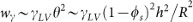 . In our simulations, wγ ~ 10−2 J/m2 and decreases with the expansion of the radius.
 -
2
wB is the driving work per unit area arising from bulk force.
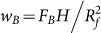 , where FB and H are the total bulk force and the height of the centre-of-mass, respectively. Set the surface of the substrate to be zero potential of the bulk force. Assuming the bulk droplet be a spherical cap, the height of the centre-of-mass of the bulk droplet equals
  . We get
 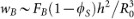 . In our simulations, wB ~ 10−2 J/m2 and mains a constant.
 -
3
wY is the resistant work per unit area arising from deformation of the pillars.
 , where I = d4/12 and δ are the moment of inertia and the average deformation of the pillars, respectively. In our simulations, wY ~ 10−3 J/m2 in the early stage, one order of magnitude less than wγ or wB. So we neglect wY in the following derivations of scaling analysis in early stage, but the effect of deformation of the pillars will be considered in the last of this paper.
 , where γSL, γSV, γLV and θ are the solid-liquid, solid-vapor and liquid-vapor interfacial energies and the instant contact angle, respectively. Taking account of the Young's equation (γSV − γSL = γLV cosθ0, θ0 is the static contact angle)
 . In the equilibrium state (wγ = 0), for a rough surface (ro > 1) we obtain the Wenzel's relation:
 . In our simulations, wγ ~ 10−2 J/m2 and decreases with the expansion of the radius.
  , where FB and H are the total bulk force and the height of the centre-of-mass, respectively. Set the surface of the substrate to be zero potential of the bulk force. Assuming the bulk droplet be a spherical cap, the height of the centre-of-mass of the bulk droplet equals
  . We get
  . In our simulations, wB ~ 10−2 J/m2 and mains a constant.
  , where I = d4/12 and δ are the moment of inertia and the average deformation of the pillars, respectively. In our simulations, wY ~ 10−3 J/m2 in the early stage, one order of magnitude less than wγ or wB. So we neglect wY in the following derivations of scaling analysis in early stage, but the effect of deformation of the pillars will be considered in the last of this paper.
 From the above discussions, w = wγ + wB − wY ~ 10−2 J/m2, the driving work wλ2 is one order of magnitude less than the thermal energy kBT. Hence, the linear approximation could be adopted  . Substituting the above results into equation (1), we obtain

From equation (2), we get a dimensionless solution  , where the characteristic time
  is controlled not only by the liquid properties (γLV, μ and R0), but also by properties of the pillars (Y, ϕs and h). When a droplet spreads on a smooth solid, the dimensionless solution is
  and the characteristic time is
  , which is only controlled by the liquid properties10,45.
Expanding the expression of R with respect to t, we obtain

In the case of the same h and Y, ϕs determines the spreading velocity. The smaller ϕs is, the faster the liquid spreads on the pillars. Validated in Fig. 3 (the darkness increases with the decrease of ϕs), the spreading of the fringe increases with the decrease of ϕs.
In the case of the same h and ϕs, Y determines the spreading velocity. For a hydrophilic LJ solid, the smaller Y is, the faster the liquid spreads on the pillars. To validate this point, we simulated a droplet on the flexible pillars by only changing Y and keeping the other quantities constant. The topology in these MD simulations is the same as sample 2 in Table 1. And we obtained the evolution of Rf with respect to t for different Y in Fig. 4(b). Obviously, the spreading of the droplet increases with the decrease of Y. The increase of Y means an increase of Wa, making the pinning to the liquid molecules and the friction at the MCL be stronger. When Y is small, i.e. Y = 36.93 or 73.90 GPa, the liquid spreading is smooth, obeying a scaling law of R ~ t1/3 shown in Fig. 3(a). When Y is large, i.e. Y = 147.8, 221.7 or 369.4 GPa, although the curves obey the scaling law of R ~ t1/3, they are not smooth. Large Y also implies large solid-liquid interaction. The pillars accelerate liquid when liquid approaches the pillars and also pin liquid when liquid passes the pillars, which makes fluctuation steps in the propagation curve.
Fig. 5(a) shows a droplet propagating on a smooth hydrophilic surface. Fig. 5(b) shows the evolution of droplet radius in polar coordinate, in which the radial, the angular coordinate and the colour represent the time evolution, the direction and the spreading distance labeled by the below colour legend, respectively. In Fig. 5(b), point A (1.5 ns, 20°, orange) represents the liquid at 20° advances about 40–45 Å in 1.5 ns. Line at 45° in Fig. 5(b) represents spreading radius of liquid at 45° with respect to time shown in Fig. 5(c), which obeys a scaling law of R ~ t1/7. The spreading of droplet on a smooth surface is nearly isotropic, i.e. independent of direction.

(a) Snapshots of the wetting of a droplet on a smooth hydrophilic surface.(b) Evolution of droplet radius R in polar coordinate. The origin O is put on the centre of the droplet. The radial and the angular coordinate represent time evolution and the direction, respectively. The colour represents the spreading distance labeled by the below colour legend. The total time is 2.5 ns. (c) Evolution of R with respect to t at 45° labeled in (b).
The spreading on the pillars depends on the arrangement of the pillars, hence is direction-dependent. The flow patterns for samples 1–4 are visualized correspondingly in Fig. 6(a–d). Because of the topographic features of the substrate, there exist fast and slow directions of the liquid flow. However, the scaling law of R ~ t1/3 is obeyed in all directions. Because the pillar arrays are symmetric, the flow pattern repeats every 45°. Comparing Fig. 6(a–d), we find the wettability gradually increase from Fig. 6(a) (more blue colour) to Fig. 6(d) (more red colour), which implies an increase of the overall velocity with the decrease of ϕs. In Fig. 6(a–d), there exist obvious boundaries distinguished by colors. The liquid advances faster in the region with more red colour and advances slower in the region with more blue colour. The boundaries of the fast and slow directions are sharp in Fig. 6(a) and gradually turn blurred in Fig. 6(d), which implies that the direction-dependence effect decreases with the decrease of roughness.

The direction-dependence of Rf with respect to t.
Samples 1–4 (a–d) with flexible pillars and (e–h) with rigid pillars. The origin O is put on the centre of the droplet. The radial and the angular coordinate represent time evolution and the direction, respectively. The colour represents the spreading distance labeled by the right colour legend. The total time is 2.5 ns.
In the last part, we discuss about the deformation of the pillars, which is neglected in the derivation of MKT in the early stage of spreading. However, the spreading velocity of the liquid is influenced by the deformation of the pillars46. To compare with the propagation of samples 1–4 with flexible pillars, we set the pillars to be rigid in the MD simulations and obtain Fig. 6(e–h). The overall velocity of Fig. 6(a–d) (more blue colour) is less than that of Fig. 6(e–h) (more red colour), because deformations of these pillars dissipate energy. With the increase of ϕs, the energy dissipation by the flexible pillars increases. Although the stiffness is changed, the fast and slow flow directions are nearly the same. The direction-dependence of the velocity is not changed.
The forces applied on and the corresponding deformation of each layer of the pillars varied with the roughness, shown in Fig. 7. To eliminate the thermal fluctuations, the forces and displacement of atoms were averaged over all the pillars and the time. In the case of large roughness (Fig. 7(a, c)), pillars are close to each other. The fringe reaches the upper and lower parts of the pillars almost at the same time, resulting in an approximately uniform distribution of the forces. The pillars bend into a quadratic curve. In the case of small roughness (Fig. 7(b, d)), pillars are far from each other. The fringe firstly reaches the lower part, then the upper part after a short time, resulting in the forces exerted on the lower layers be a little larger than those on the upper layers. The pillars bend into a sigmoidal curve.

The averaged displacement of and force on each layer of the pillars for (a) ro = 2.65, (b) ro = 1.89, (c) ro = 2.78 and (d) ro = 2.04.
The gray and orange circles represent the initial and final positions, respectively.
In summary, the dynamics of a droplet on the flexible hydrophilic pillars is explored using large scale MD simulations. For the first time, the combined effect of the surface topology, the intrinsic wettability and the elasticity of a solid on the dynamic wetting is taken into consideration. The atomic details of both the liquid and the pillars during the superwetting, especially at the MCL, are revealed. The flexible pillars accelerate the liquid when the liquid approaches, while also pin the liquid when the liquid passes. The direction-dependent spreading of the liquid deforms the pillars, resulting in energy dissipation at the MCL. Our results may help to understand the dynamic wetting of the droplet on flexible pillar-arrayed substrate and assist the future design of active control of wetting in practical applications.
Methods
Molecular dynamics simulations
Large-scale MD simulations implemented in LAMMPS27 were carried out to explore the dynamic wetting process of a droplet on flexible hydrophilic pillar-arrays at the atomic level. The total potential energy Eij between two atoms i and j separated by rij is the sum of Lennard-Jones (LJ) potential energy and the Coulombic pairwise interaction

where ε is the depth of the potential well, σ is the zero-crossing distance for the potential, ke = 8.988 × 10⁹ N·m2/C2 is the Coulomb constant and q is the charge on atom. The cut-off length for LJ potential is 1.5 nm, while that for Coulombic interaction is 1.0 nm.
The NVT ensemble (constant number of atoms, volume and temperature) was used. The Nosé-Hoover thermostat, acting as a heat reservoir, with a time-step of 1 fs was employed to regulate the temperature at 350 K. The simulation domain is about 15 × 15 × 20 nm3 according to the arrangement of pillars.
The water molecules were simulated using the simple point charge/extended (SPC/E) water model: the oxygen atoms were modeled as charged LJ particles (σO−O = 0.3166 nm, εO−O = 0.650 kJ/mol, qO = −0.8476 e), while the hydrogen atoms were charged but without considering LJ interactions between them (σH−H = 0.0 nm, εH−H = 0.0 kJ/mol, qH = 0.4238 e). The solid atoms were modeled as uncharged LJ particles with σS−S = 0.2637 nm and εS−S = 42.5723 kJ/mol, which were chosen to be hydrophilic to the SPC/E water. The values of σ and ε between them were calculated according to the Lorentz-Berthelot rule:  and
and  , where the subscripts X and Y represent the types of atoms. So σO−H = 0.1583 nm, σS−H = 0.1319 nm, σS−O = 0.2902 nm and εO−H = 0.0 kJ/mol, εS−H = 0.0 kJ/mol, εS−O = 5.2604 kJ/mol. The LJ interactions between hydrogen and oxygen atoms, as well as between hydrogen and solid atoms were ignored. The cut-off length for LJ potential is 1.5 nm, while that for Coulombic interaction is 1.0 nm.
The SPC/E model was established by adding an average polarization correction to the SPC model, with a modified value of qO (charge of oxygen atom) and qH (charge of hydrogen atom). Compared with SPC, transferable intermolecular potential 3 point (TIP3P), TIP4P, TIP5P water model, SPC/E model predicted a better density (ρ = 994 Kg/m3), viscosity (μ = 0.729 mPa·s)28 and surface tension (γLV = 0.0636 N/m)29, which are close to those of the real bulk water.
References
Joanny, J. F. & de Gennes, P. G. A model for contact angle hysteresis. J. Chem. Phys. 81, 552 (1984).
Bonn, D., Eggers, J., Indekeu, J., Meunier, J. & Rolley, E. Wetting and spreading. Rev. Mod. Phys. 81, 739–805 (2009).
Král, P. & Wang, B. Material Drag Phenomena in Nanotubes. Chem. Rev. 10.1021/cr200244h (2013).
Sun, T., Feng, L., Gao, X. & Jiang, L. Bioinspired surfaces with special wettability. Acc. Chem. Res. 38, 644–652 (2005).
Balaban, N. Q. et al. Force and focal adhesion assembly: a close relationship studied using elastic micropatterned substrates. Nat. Cell Biol. 3, 466–472 (2001).
Yang, M. T., Fu, J., Wang, Y. K., Desai, R. A. & Chen, C. S. Assaying stem cell mechanobiology on microfabricated elastomeric substrates with geometrically modulated rigidity. Nat. Protoc. 6, 187–213 (2011).
Quéré, D. Wetting and roughness. Annu. Rev. Mater. Res. 38, 71–99 (2008).
Bocquet, L. & Lauga, E. A smooth future? Nat. Mater. 10, 334–337 (2011).
McHale, G., Shirtcliffe, N., Aqil, S., Perry, C. & Newton, M. Topography driven spreading. Phys. Rev. Lett. 93, 36102 (2004).
Yuan, Q. Z. & Zhao, Y. P. Multiscale dynamic wetting of a droplet on a lyophilic pillar-arrayed surface. J. Fluid Mech. 716, 171–188 (2013).
Du Roure, O. et al. Force mapping in epithelial cell migration. Proc. Nat. Acad. Sci. USA 102, 2390–2395 (2005).
Tan, J. L. et al. Cells lying on a bed of microneedles: an approach to isolate mechanical force. Proc. Nat. Acad. Sci. USA 100, 1484–1489 (2003).
Edwards, C. M. & Schwarz, U. S. Force localization in contracting cell layers. Phys. Rev. Lett. 107, 128101 (2011).
Ishino, C., Reyssat, M., Reyssat, E., Okumura, K. & Quéré, D. Wicking within forests of micropillars. Europhys. Lett. 79, 56005 (2007).
Tsai, P., Lammertink, R. G. H., Wessling, M. & Lohse, D. Evaporation-Triggered Wetting Transition for Water Droplets upon Hydrophobic Microstructures. Phys. Rev. Lett. 104, 116102 (2010).
Papadopoulos, P., Mammen, L., Deng, X., Vollmer, D. & Butt, H.-J. How superhydrophobicity breaks down. Proc. Nat. Acad. Sci. USA 110, 3254–3258 (2013).
Chen, X. et al. Evaporation of Droplets on Superhydrophobic Surfaces: Surface Roughness and Small Droplet Size Effects. Phys. Rev. Lett. 109, 116101 (2012).
Xu, W. & Choi, C.-H. From Sticky to Slippery Droplets: Dynamics of Contact Line Depinning on Superhydrophobic Surfaces. Phys. Rev. Lett. 109, 024504 (2012).
Rothstein, J. P. Slip on superhydrophobic surfaces. Annu. Rev. Fluid Mech. 42, 89–109 (2010).
Courbin, L. et al. Imbibition by polygonal spreading on microdecorated surfaces. Nat. Mater. 6, 661–664 (2007).
Hashmi, A. et al. Leidenfrost levitation: beyond droplets. Sci. Rep. 2, 797 (2012).
Wang, B. Y. & Král, P. Chemically tunable nanoscale propellers of liquids. Phys. Rev. Lett. 98, 266102 (2007).
Wang, C. L. et al. Stable Liquid Water Droplet on a Water Monolayer Formed at Room Temperature on Ionic Model Substrates. Phys. Rev. Lett. 103, 137801 (2009).
Wang, C. et al. Critical Dipole Length for the Wetting Transition Due to Collective Water-dipoles Interactions. Sci. Rep. 2, 358 (2012).
Yuan, Q. Z. & Zhao, Y. P. Precursor film in dynamic wetting, electrowetting and electro-elasto-capillarity. Phys. Rev. Lett. 104, 246101 (2010).
Chu, K. H., Xiao, R. & Wang, E. N. Uni-directional liquid spreading on asymmetric nanostructured surfaces. Nat. Mater. 9, 413–417 (2010).
Plimpton, S. Fast Parallel Algorithms for Short-Range Molecular-Dynamics. J. Comput. Phys. 117, 1–19 (1995).
González, M. A. & Abascal, J. L. F. The shear viscosity of rigid water models. J. Chem. Phys. 132, 096101 (2010).
Vega, C. & de Miguel, E. Surface tension of the most popular models of water by using the test-area simulation method. J. Chem. Phys. 126, 154707 (2007).
Yuan, Q. Z. & Zhao, Y. P. Topology-dominated dynamic wetting of the precursor chain in a hydrophilic interior corner. Proc. R. Soc. A 468, 310–322 (2012).
Patra, N., Wang, B. Y. & Král, P. Nanodroplet Activated and Guided Folding of Graphene Nanostructures. Nano Lett. 9, 3766–3771 (2009).
Zhu, X. Y., Yuan, Q. Z. & Zhao, Y. P. Capillary wave propagation during the delamination of graphene by the precursor films in electro-elasto-capillarity. Sci. Rep. 2, 927 (2012).
Blake, T. D. The physics of moving wetting lines. J. Colloid Interface Sci. 299, 1–13 (2006).
Frenkel, J. Kinetic theory of liquids. (Oxford university press, 1946).
Glasstone, S., Laidler, K. & Eyring, H. The Theory of Rate Processes. (McGraw-Hill, 1941).
Blake, T. D. & de Coninck, J. The influence of solid-liquid interactions on dynamic wetting. Adv. Colloid Interface Sci. 96, 21–36 (2002).
Van der Hoef, M. A. Free energy of the Lennard-Jones solid. J. Chem. Phys. 113, 8142 (2000).
Van de Waal, B. W. Can the Lennard-Jones solid be expected to be fcc? Phys. Rev. Lett. 67, 3263–3266 (1991).
Israelachvili, J. Intermolecular and Surface Forces. (Academic press, 1992).
Kim, S. J. et al. Liquid spreading on superhydrophilic micropillar arrays. J. Fluid Mech. 680, 477–487 (2011).
Greenspan, H. On the motion of a small viscous droplet that wets a surface. J. Fluid Mech. 84, 125–143 (1978).
Ehrhard, P. & Davis, S. H. Non-isothermal spreading of liquid drops on horizontal plates. J. Fluid Mech. 229, 365–388 (1991).
Young, T. An essay on the cohesion of fluids. Philos. Trans. R. Soc. London 95, 65–87 (1805).
Wenzel, R. N. Resistance of solid surfaces to wetting by water. Ind. Eng. Chem. 28, 988–994 (1936).
De Gennes, P. G. Wetting: statics and dynamics. Rev. Mod. Phys. 57, 827–863 (1985).
Duprat, C., Protiere, S., Beebe, A. & Stone, H. Wetting of flexible fibre arrays. Nature 482, 510–513 (2012).
Acknowledgements
This work is jointly supported by the National Natural Science Foundation of China (NSFC, Grant No. 11202213 and No. 11072244), the Key Research Program of the Chinese Academy of Sciences (Grant No. KJZD-EW-M01) and the Instrument Developing Project of the Chinese Academy of Sciences (Grant No. Y2010031).
Author information
Authors and Affiliations
Contributions
Both Q.Z.Y. and Y.P.Z. contributed the ideas, performed the numerical simulations, carried out the theoretical analysis, wrote the paper, discussed the results and commented on the manuscript.
Ethics declarations
Competing interests
The authors declare no competing financial interests.
Rights and permissions
This work is licensed under a Creative Commons Attribution-NonCommercial-NoDerivs 3.0 Unported License. To view a copy of this license, visit http://creativecommons.org/licenses/by-nc-nd/3.0/
About this article
Cite this article
Yuan, Q., Zhao, YP. Wetting on flexible hydrophilic pillar-arrays. Sci Rep 3, 1944 (2013). https://doi.org/10.1038/srep01944
Received:
Accepted:
Published:
DOI: https://doi.org/10.1038/srep01944
This article is cited by
-
The effect of surface anisotropy on contact angles and the characterization of elliptical cap droplets
Science China Technological Sciences (2018)
-
Molecular origin of contact line stick-slip motion during droplet evaporation
Scientific Reports (2015)
-
Nanoparticle-tuned spreading behavior of nanofluid droplets on the solid substrate
Microfluidics and Nanofluidics (2015)
-
Dewetting Properties of Metallic Liquid Film on Nanopillared Graphene
Scientific Reports (2014)
Comments
By submitting a comment you agree to abide by our Terms and Community Guidelines. If you find something abusive or that does not comply with our terms or guidelines please flag it as inappropriate.
