
Key Points
-
Aims to introduce the general dental practitioner to the armamentarium of implant dentistry and provide instructions for making accurate impressions in implant retained prosthodontics.
-
The reader will understand the need for various techniques and appreciate the use of abutments and verification jigs.
-
Clinical tips related to impression making are included.
Abstract
Accurate impressions provide a foundation for successful implant prosthodontics. This paper is aimed at the general dental practitioner (GDP) who would like to start restoring dental implants and demystifies the terminology, introduces the basic armamentarium and discusses the relative merits of different implant impression techniques. Detailed, step-by-step instructions for making impressions using the closed and open tray techniques are provided and the importance of verification jigs are highlighted.
Clinical relevance A successful restoration is dependent upon proper planning and meticulous clinical processes. An understanding of impression techniques is therefore fundamental for the GDP wishing to restore implant-supported prostheses.
Objectives The reader should be familiar with different implant components and understand the impression techniques used in implant dentistry.
Introduction
Dental implants can be used to retain single crowns, fixed partial dentures, full arch bridgework and removable prostheses. The use of dental implants is well established1 and high survival rates have been reported.2,3,4,5,6 Implant dentistry now forms a significant part of general dental practice and patient awareness is steadily increasing. Dental practitioners may be involved in the planning, placement and restoration of dental implants and an accurate impression is vital if the patient is to be provided with a successful prosthesis. The object of making an impression in implant dentistry is to accurately relate the position of the most coronal portion of the implant (implant fixture head) to other structures within the oral cavity. Once fabricated, the clinician has to ensure that the prosthesis is seated correctly and fits passively, as a passive fit is essential for long-term treatment success.7,8 This paper is aimed at the GDP with little or no experience in restoring dental implants and introduces the basic armamentarium, demystifies terminology and describes different implant impression techniques.
Armamentarium
To effectively carry out any procedure, it is crucial to familiarise oneself with the components involved. Invariably, the first step is to determine the implant system used (eg Nobel Replace, Nobel Brånemark System, AstraTech Osseospeed, Straumann SLActive, etc) (Fig. 1), as this will dictate the type of impression components used. Identification of the implant system used is not always easy and may involve obtaining previous case notes, radiographic assessment and/or direct visualisation of the fixture head, which is usually at the level of the alveolar crest. Each implant system has its own set of impression components that are designed to fit accurately onto the fixture head of the implant, which is machined to specific geometry. Irrespective of the implant system used, the impression components and techniques are broadly very similar.

Nobel Replace fixture heads (a) and a Brånemark fixture head (b)
Impression tray
Similar to crown and bridge prosthodontics, impression trays can either be stock trays or custom made trays. Custom trays are preferred as they are generally more rigid and permit the impression material to be used in its optimal thickness. In implant prosthodontics, trays can further be classified as open (Fig. 2) or closed (Fig. 3). An open tray permits direct access to the implant fixture head with the tray seated intra-orally. The advantages and disadvantages of these techniques will be discussed later in this article.

Open custom tray

Closed custom tray
Custom tray design
A custom tray can be used to make an impression at fixture head level, abutment level or both within the same impression. A primary impression is a prerequisite for the construction of the custom tray. Careful examination of the primary model will give a good indication of the position and angulation of the implants. The clinician should provide the technician with their choice of impression material, so that the appropriate spacer can be laid down. The authors recommend the use of rigid acrylic resin as the custom tray material.
Impression materials
The impression material used should be easy to mix, accurate, rapidly setting and dimensionally stable following removal from the mouth. The materials that fulfil these criteria are Quadrafunctional Vinyl polysiloxanes silicones (eg Aquasil Ultra, Dentsply, UK); Addition Cured Silicones (eg Extrude, Kerr, UK) and Polyethers (eg Impregum, 3M ESPE, UK).9 Ultra-low expansion plaster (eg Gnathastone, Zeus) can be useful due to its rigidity, but care should be taken to block out all undercuts before making the impression.
Screwdrivers
An implant screwdriver is a critical piece of equipment used to screw and unscrew various components onto the fixture head. Depending on the implant system, screwdrivers heads can be slotted, hexagonal, star shaped, etc (Fig. 4). Screwdrivers are often designed to fit into a manual or motor driven torque device, which can be used to tighten components to a predetermined torque (Fig. 5).

Screwdrivers (from left to right) with a hexagonal head (AstraTech) and star shaped heads (Straumann and Nobel Biocare)

Manual torque device (Nobel Biocare)
Healing abutment/caps
The fixture head is usually at the level of the alveolar bone crest, therefore, in order to provide access to the fixture head, a removable transmucosal component known as a healing abutment/cap (Fig. 6) is screwed onto the fixture head by the surgeon, either at the time of implant placement or as a second surgical procedure. Healing abutments/caps vary in height, width and profile. An appropriate healing abutment is selected to mould the peri-implant tissues during healing and prevent tissue overgrowth.

AstraTech healing abutments
When ordering a custom tray, it is important to provide information regarding the height of the healing abutment, to ensure that the technician can estimate the thickness of the soft tissues and provide adequate space for the requisite components.
Impression coping
The impression coping is the component that fits onto the implant fixture head or an implant abutment (discussed later) while making an impression. Broadly speaking, there are two types of impression copings: one that is used with a closed tray and retained in the mouth after the impression is removed (Fig. 7a) and the second, used with an open custom tray, in which the impression is removed with the coping in situ within the impression (Fig. 7b). Once cast, the impression copings transfer the position of the implant fixture head/abutment onto the working model.

Nobel Replace closed tray impression coping (a), AstraTech open tray fixture level impression coping (b)
Certain clinical situations, eg unfavourably positioned implants, the need to support adjacent soft tissues, poor access, etc dictate the need for a custom impression coping.10 Custom copings are often conventional copings, which have been modified by trimming or by roughening and adding acrylic resin (Figs 8a-c). While trimming and roughening the impression coping, care should be taken not to damage the portion of the impression coping that engages within the fixture head. This can be done by screwing the impression coping onto an implant replica while trimming. Once trimmed, the authors prefer to screw the impression coping into the implant and add flowable composite into the space between the coping and soft tissues. It is important to ensure that there is haemostasis during the addition of composite. Following the initial composite addition, further increments can be made either with the impression coping in situ or extraorally, until the soft tissues are adequately supported.

An impression coping modified by the addition of acrylic resin to maintain the position of the soft tissues during impression taking (a), the coping in the mouth (b) and in the impression (c)
Abutments
When implant positioning is optimal the prosthetic superstructure can be screwed directly on the fixture head. However, this is not possible if the implant angulation is unfavourable, the fixture head is deeply placed or implants are divergent. In these circumstances, implant angulation or depth can be corrected with an intermediary abutment. These are available in a variety of materials (eg titanium, zirconia, etc.) and the implant superstructure is subsequently screwed or cemented to these abutments.
Prefabricated stock abutments
Prefabricated stock abutments are off-the-shelf components produced in a variety of collar heights, widths and angulations. These are available in titanium, gold and ceramic and can be screwed (or press fitted with some systems) directly to the fixture head before impression making. Some standard abutments come with individual impression copings (eg Easy Abutment, Snappy Abutment, etc, Nobel Biocare)(Fig. 9). Alternatively, an impression of the prefabricated abutment can be made using conventional crown and bridge impression techniques.

Definitive standard abutments (Easy Abutment, Nobel Biocare) seated (a), impression copings placed on abutments (b) and the final prosthesis (c)
Prefabricated abutments must be carefully selected with the final prosthesis in mind. Abutment analogues can be useful to select the correct standard abutment. Where multiple implants are involved it is often necessary to select standard abutments following analysis of a fixture head model. Prefabricated abutments are relatively cheap and they simplify impression making by moving the restoration margin coronally. However, they come in a relatively limited number of shapes and sizes and are inappropriate in all circumstances, especially when the fixture head is deeply subgingival.
For implant retained overdentures, prefabricated abutments with a variety of attachment mechanisms (eg ball, magnets, LOCATOR, etc) (Fig. 10) are available in a series of different heights and widths, with its own specifically designed impression coping (Fig. 11).

LOCATOR abutments

Impression copings on LOCATOR abutments
Custom abutments
Custom abutments, individualised for each restoration, can be used where prefabricated abutments are inadequate. They are often made using CAD/CAM techniques and are available in a variety of metals and ceramics (Fig. 12). Custom abutments are generally more expensive than prefabricated abutments. However, they can be designed so that the abutment-crown junction is hidden to ensure superior aesthetics.

Crown margin is hidden subgingivally
One-piece implants
One-piece implants (Figs 13a-d) incorporate an integral abutment. This abutment is usually prepared using special burs designed to cut titanium. Care must, however, be taken to ensure that the implant is not overheated and the abutment is not excessively reduced. A conventional crown and bridge impression is made of the prepared abutment. These one-piece implants can be obtained in narrow diameters and are particularly useful in the replacement of mandibular incisors. However, abutment preparation is irreversible therefore the long-term prognosis of adjacent teeth must be carefully considered as the implant may need to be used as a part of a bridge in the future.

A single piece dental implant (Nobel Direct) being placed (a), the palatal portion of the abutment was prepared (b), extraoral view following implant placement (d) and the provisional crown in place (d)
Impression techniques
Two techniques are commonly employed to make an impression of the fixture head: the closed tray and open tray techniques.
Closed tray technique (Fig. 14a-f)
The healing abutment/cap is removed with a screwdriver and the implant fixture head is exposed (Fig. 14a).
-
1
A closed-tray impression coping, appropriate to the type and size of implant, is selected and fitted onto the exposed fixture head (Fig. 14b). If the clinician is unsure about the complete seating of the coping onto the fixture head, a confirmatory radiograph should be taken11
-
2
An appropriate stock tray or a closed custom tray is tried in. It is important to ensure that the tray covers the entire arch, provides adequate vertical space for the impression coping and optimum space for the impression material
-
3
The authors generally use a combination of light bodied and heavy bodied silicone in a manner similar to conventional crown and bridge impressions (Fig. 14c-d). Care must, however, be taken not to use too much light bodied material as it tends to be less rigid and may affect the repositioning of the impression coping
-
4
Once set, the impression is removed, leaving the impression coping in the mouth (Fig. 14e)
-
5
The impression coping is then removed and manually repositioned into the impression (Fig. 14f). It is important that the coping relocates positively and it is critical to ensure that the geometric details of the impression coping is recorded accurately in the impression (Fig. 15)
Figure 15 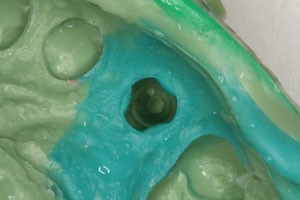
Detail of the impression coping recorded in a closed tray impression
-
6
The healing abutment is replaced.


Closed tray technique: exposed fixture head after removal of the healing abutment (a), closed tray impression coping screwed in place (b), light bodied impression material syringed around impression coping (c), impression taken in a stock tray (d), impression with details of soft tissue around the implant and adjacent teeth (e) and impression coping repositioned into the impression (f)
Plastic impression copings that press-fit onto the fixture head may be used with the closed tray technique (Fig. 16). These copings get embedded within the impression material and are removed from the mouth in situ within the impression. However, there is a small risk of dislodging the impression coping during impression taking and removal.

Plastic impression copings
Open tray technique (Fig. 17a-d)
At the preliminary appointment:
-
1
A conventional alginate impression is made and study models are cast
-
2
A rigid custom tray is manufactured with a window cut through over the implant (see section of tray design for further detail).
At a subsequent appointment:
-
1
The healing abutments are removed
-
2
Appropriate impression copings are selected and fitted (Figs 17a). In some cases, these copings may be splinted together intraorally to provide greater rigidity and possibly greater accuracy
Figure 17 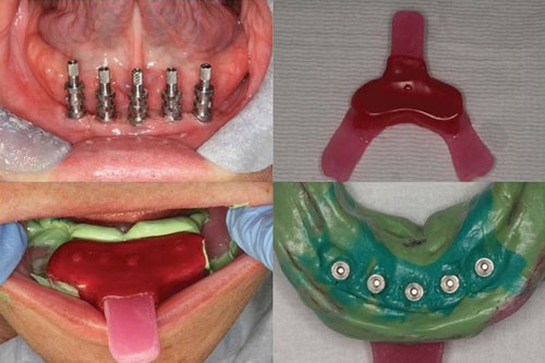
Open tray impression technique: impression copings in place (a), open custom tray with window sealed with wax (b), impression in place with the tips of the impression copings projecting through the wax window (c), the completed impression with the impression copings in situ (d)
-
3
The open tray is tried in – the impression copings should emerge level with the window. This permits easy removal of the impression copings, while ensuring that the copings are supported by sufficient impression material
-
4
The window is sealed with wax (Fig. 17b)
-
5
An impression is taken in the open tray with a silicone impression material. The tips of the impression copings should be felt through the wax covering the window (Fig. 17c)
-
6
Once the impression has set, the impression copings are unscrewed through the window on the tray and the impression is removed from the mouth along with all the impression copings in place (Fig. 17d)
-
7
The healing abutments are replaced.

Open tray versus closed tray
The authors have found that a closed tray impression technique is generally simpler and quicker but involves reseating the impression coping, which may introduce potential inaccuracies.12,13
A recent systematic review on impression techniques showed that in situations where there are three or fewer implants, there was no difference between an open tray and closed tray approach. However, if there were four or more implants, impressions appeared more accurate with an open tray technique.14 Several authors have suggested splinting of impression copings to improve impression accuracy, however, this appears less critical for internal connection implants.15 An open tray technique is specifically indicated where implants are divergent as it may not be possible to remove a closed tray in these situations.16 However, an open tray technique may not be suitable if the patient has an exaggerated gag reflex, has restricted mouth opening or if there is limited access eg posterior dentition.
Abutment impressions
Within general dental practice, there is often a need to replace an implant crown, which is aesthetically unsatisfactory, while the underlying abutment is satisfactory. In these situations, a routine crown and bridge approach may be employed, ie the gingivae may be retracted using displacement cord (Fig. 18) or alternative methods (eg Expasyl, Kerr UK) and a conventional impression in a rigid tray may be made. Care must be taken not to damage the fragile epithelial attachment to the abutment. The crown/bridgework can then be made and cemented onto the abutments.

Gingival tissue management around zirconia abutments using retraction cord
Alternately, the implant crown can be overcontoured along the gingival margin by adding a small amount of composite resin, following which the crown is reseated for 5–10 minutes. This will displace the gingival tissue and permit an accurate impression of the abutment to be made. This technique has the advantage of not disrupting the epithelial attachment around the abutment.
Implant analogues, disinfection and laboratory procedures
Once an impression has been made, the impression should be thoroughly inspected. All teeth should be accurately recorded to allow future articulation and replication of contralateral tooth contours. The impression coping should be securely located within the impression. Implant replicas or analogues are attached to the impression coping before casting the impression (Fig. 19). The replicas get embedded within the model and reproduce the positions and geometry of the implant fixture heads. The clinician should carefully attach the implant replica, taking care to avoid any rotation of the impression coping.

Implant replica seated within an open tray impression (a), Nobel Replace implant replicas – with and without an impression coping (b)
All impressions should be disinfected in accordance with the recommendations of the British Dental Association (BDA advice sheet A12).17 This advice includes immediate rinsing of the impression to remove saliva, blood and debris, followed by immersion in an appropriate disinfectant for the recommended time period. The impression should be rinsed once again before sending it to the laboratory. Dispatching the impression in a sealed box, rather than a polythene bag will ensure that they are not damaged and delicate components are not dislodged.
The prescription to the laboratory should include details of the implant system, type of restoration required (ie temporary or definitive crown, etc), choice of material for the crown and abutment and shade. Often, a small volume of soft silicone is poured directly into the impression (Fig. 20a) around the impression coping in order to mimic gingival tissues (Fig. 20b). This is done to permit the removal and replacement of the gingival tissues, thus providing access to the fixture head, without damaging the model. The technician has to be careful not to cover the implant replicas or any of the adjacent teeth with the soft silicone as this may introduce errors.

Silicone mimicking gingival tissues being syringed around the implant replicas (a), working model with removable silicone cuff around implants (b)
Model verification
Where multiple implants are to be linked, it is good practice to verify the accuracy of the working model, before constructing expensive superstructures, with a verification jig.
A verification jig consists of titanium cylinders that are screwed onto the implant replicas on the model and linked with acrylic resin (DuraLay). Care is taken to ensure that this jig fits passively on the model and that there are no gaps between the titanium cylinders and implant replicas.
The verification jig is then tried-in intraorally (Fig. 21), to verify the accuracy of the model. Care must be taken to verify that the titanium cylinders seat completely and passively on the fixture head. The fit of the verification jig can be verified by (a) manual palpation, (b) the Sheffield one screw test, (c) dental floss or (d) a disclosing medium.17 Where the implants lie below the alveolar mucosa, a radiograph may be required.

Verification jig tried intraorally
A poorly fitting jig indicates a discrepancy between the positions of the implants intraorally and on the model. If this situation arises, the jig will need to be sectioned around the inaccurate implant and repaired intraorally using cold cure resin. The position of the implant can then be picked up onto the jig and the master model can be modified accordingly. Alternately the impression can be repeated. To minimise inaccuracies, the authors recommend repeating the impression.
Summary
Accurate impressions and meticulous attention to detail provide a foundation for successful implant prosthodontics. A comprehensive understanding of the range of prosthetic components is essential and often gained only by clinical experience. Open and closed tray techniques have their respective merits and drawbacks and the choice of technique employed can be down to clinician preference. Inaccuracies can be minimised by ensuring that the implant replicas are placed onto the impression coping by the clinicians themselves and also by the use of verification jigs.
References
Scheller H, Urgell J, Kultje C et al. A 5-year multicentre study on implant supported single crown restorations. Int J Oral Maxillofac Implants 1998; 13: 212–218.
Levin L, Laviv A, Schwartz-Arad D . Long term success of implants replacing a single molar. J Periodontol 2006; 77: 1528–1532.
Levin L, Sadet P, Grossmann Y . A retrospective evaluation of 1,387 single tooth implants: a 6-year follow up. J Periodontol 2006; 77: 2080–2083.
Pjetursson B E, Tan K, Lang N et al. Systematic review of the survival and complication rates of fixed partial dentures after an observation period of atleast 5 years. I – Implant supported FPDs. Clin Oral Implant Res 2004; 15: 625–642.
Brånemark P I, Svensson B, van Steenberghe D . Ten year survival rates of fixed prostheses on four or six implants ad modum Brånemark in full edentulism. Clin Oral Implant Res 1995; 6: 227–231.
Sadowsky S . Treatment considerations for maxillary implant overdentures: a systematic review. J Prosthet Dent 2007; 97: 340–348.
Jemt T, Lie A . Accuracy of implant supported prostheses in the edentulous jaw: analysis of precision of fit between cast gold alloy frameworks and master casts by means of a three dimensional photogrammetric technique. Clin Oral Implant Res 1995; 6: 172–180.
Millington N D, Leung T . Inaccurate fit of implant superstructures. Part 1: Stresses generated in the superstructure relative to the size of fit discrepancy. Int J Prothodont 1995; 8: 511–516.
van Noort R . Introduction to dental materials. 3rd ed. Mosby, 2007.
Spyropoulou, P-E, Razzoog M, Sieraalta M . Restoring implants in the aesthetic zone after sculpting and capturing the periimplant tissues in rest position: a clinical report. J Prosthet Dent 2009; 102: 345–347.
Chee W, Jivraj S . Impression techniques for implant dentistry. Br Dent J 2006; 201: 429–432.
Phillips K, Nicholls J I, Tsun M, Rubenstein J E . The accuracy of three implant impression techniques: a three dimensional analysis. Int J Oral Maxillofac Implants 1994; 9: 533–540.
Lee Y J, Heo S J, Koak J Y, Kim S K . Accuracy of different impression techniques for internal connection implants. Int J Oral Maxillofac Implants 2009; 24: 823–830.
Lee H, So J S, Hochstedler J L, Ercoli C . The accuracy of implant impressions: a systematic review. J Prosthet Dent 2008; 100: 285–291.
Kan J, Rungcharassaeng K, Bohsali K et al. Clinical methods for evaluating implant framework fit. J Prosthet Dent 1999; 81: 7–13.
Nobel Esthetics. Products and procedures manual. Nobel Biocare Services, AG, 2010.
British Dental Association. BDA advice sheet A12: Infection control in dentistry. http://www.bda.org.
Acknowledgements
The authors would like to thank Mr Nigel Rosenbaum, Specialist in Prosthodontics, for the images in Figure 9.
Author information
Authors and Affiliations
Corresponding author
Additional information
Refereed paper
Rights and permissions
About this article
Cite this article
Bhakta, S., Vere, J., Calder, I. et al. Impressions in implant dentistry. Br Dent J 211, 361–367 (2011). https://doi.org/10.1038/sj.bdj.2011.862
Accepted:
Published:
Issue Date:
DOI: https://doi.org/10.1038/sj.bdj.2011.862
This article is cited by
-
Implant retention systems for implant-retained overdentures
British Dental Journal (2017)
