
Abstract
Recent advances in the neural stem cell field have provided a wealth of methods for generating large amounts of purified neuronal precursor cells. It has become a question of paramount importance to determine whether these cells integrate and interact with established neural circuitry after engraftment. In principle, neurons have to fulfill three basic functions: receive incoming signals via synapses, compute and forward processed information to other neurons or effector cells. It is anticipated that functionally integrating stem cell-derived donor neurons perform accordingly. Here we provide protocols for the efficient electrophysiological evaluation of engrafted cells and highlight current limitations thereof.
Introduction
During the last few years, we have begun to understand how to derive defined subsets of neuronal progeny from stem cells in vitro. These neurons can be tailored, in cell culture, to display striking morphological and immunophenotypic similarities to cells found in the adult brain, and even to cells lost during the course of brain disease1,2,3,4,5,6,7,8,9,10. Because stem cell-derived neurons are born in a culture dish, without the environmental cues of the developing brain, it has become a major quest to determine whether these cells are actually functional, that is, capable of interacting with established neural circuitry. This information is crucial and a key prerequisite for a wide spectrum of applications, such as pharmacological screens or reconstructive cell therapy11,12,13,14,15. However, until now, there is no clear description available that specifies basic procedures to validate the functional integration of stem cell-derived neurons into a host tissue.
Here we present a protocol that could serve as a blueprint to assess the function of engrafted stem cell-derived neurons. Although patch-clamp techniques represent an integral part of the evaluation process, this manuscript does not intend to recite basic knowledge of experienced electrophysiologists16,17,18. We would rather like to highlight the implications and current limitations thereof.
Overview on the procedure
The protocol presented here should be particularly useful for those investigators who have already characterized the morphological and immunocytochemical phenotype of their stem cell-derived neuronal population and would now like to move on to a functional analysis. At this stage, patch-clamp profiling of engrafted donor-derived neurons would represent the next validation step toward application in a variety of experimental paradigms. A reasonable approach is recording from cells grafted into established neural circuitries that provide specific environmental cues and at the same time enable the analysis of donor–host and host–donor interactions.
There are a variety of platform technologies to obtain functional data from living donor cells in situ. One technique for delivering donor cells into the host brain parenchyma is intrauterine transplantation (Box 1; Fig. 1), involving direct injection of migratory active donor cells into the ventricles of the fetal murine brain. This approach permits integration of donor cells in a large variety of brain regions. Early postnatal transplantation, too, has been shown to yield widespread engraftment, although donor cell migration and incorporation are more restricted than during fetal development. Owing to the early time point of implantation, both procedures can be performed without the need of immunosuppression—an issue especially useful for xenograft experiments19,20,21,22. Other transplantation paradigms require precautions for minimizing the risk of rejection of non-syngeneic donor cells, for example (i) the use of immunosuppression (e.g., daily injections of 5–20 mg kg−1 cyclosporine into the peritoneal space or the nuchal fold; Sandimmun, Sandoz), (ii) cell engraftment into immunocompromised hosts (e.g., severe combined immunodeficiency mice), or (iii) the use of brain tissue explants as recipients for in vitro transplantation23,24. The third technology additionally serves as a useful tool for studying the maturation and integration of donor cells in controlled, real-time scenarios. Crucial for studying vital donor cells in recipient tissues is the availability of genetically labeled donor cells that are readily identifiable in situ by expression of fluorescent indicator proteins (e.g., enhanced green fluorescent protein (EGFP)), under the control of either cell-type specific or constitutively active promoters25,26,27,28,29,30.

(a) Transuterine injection into the telencephalic vesicle of a rat fetus (E-17). (b) Schematic representation of the transplant approach. After injection into the cerebral ventricles of the rat embryos, the donor cells distribute throughout the ventricular system. Abbreviations: C, injection capillary; F, fiber optic light source; H, experimenter's thumbs; U, uterus. Reproduced with permission from Brüstle et al.53,54.
The viability of targeted donor cells can be assessed (e.g., in brain slice preparations) by establishing appropriate patch-clamp conditions with seal resistances >1 GΩ, and via analysis of passive membrane characteristics. Because stem cell-derived neurons undergo a characteristic developmental progression of biophysical membrane properties23, it is difficult to project the expected ranges for these values. However, as a rule of thumb, viable donor cells should display stable input resistances (Rin) and constant-negative resting membrane potentials (RMPs) throughout a minimum recording period of approximately 20 min. Key prerequisite for functional integration of donor-derived neurons is the establishment of physical contacts to host cells enabling synaptic transmission, which can be assessed as described in the main protocol below.
Materials
Reagents
-
Rats harboring transplanted cells (see Box 1 for a possible transplantation protocol) for acute slice preparation from brain tissue, or rat pups to prepare brain slice cultures
Caution
Animal experiments must conform to the respective institutional and national regulations.
-
For slice cultures, a single-cell suspension of donor cells, concentrated to 105 cells μl−1 in DMEM/F12 and stored on ice in a small, sterile Eppendorf tube
Critical
Required if performing donor transplantation.
-
CaCl2·2H2O (Sigma)
-
D-Glucose (Sigma)
-
EGTA (Sigma)
-
HEPES (Sigma)
-
KCl (Sigma)
-
K-gluconate (Sigma)
-
KOH (Sigma)
-
Mg-ATP (Sigma)
-
MgCl2·6H2O (Sigma)
-
NaCl (Sigma)
-
Na-GTP (Sigma)
-
NaH2PO4·H2O (Sigma)
-
NaHCO3 (Sigma)
-
Neurobiotin (Vector)
-
70% ethanol (v/v)
-
Sterile PBS (Invitrogen)
-
Sterile DMEM/F12 (Invitrogen)
Equipment
-
Vibration isolation table and Faraday cage (for electrophysiology)
-
Microscope (for electrophysiology)
-
Video camera and monitor (for electrophysiology)
-
Slice chamber (for electrophysiology)
-
Perfusion line and heating (for electrophysiology)
-
Micromanipulators (for electrophysiology)
-
Patch-clamp amplifier (e.g., HEKA, Molecular Devices) (for electrophysiology)
-
AD/DA converter (e.g., HEKA, Molecular Devices) (for electrophysiology)
-
Computer running data acquisition software, several commercial solutions are available (e.g., HEKA, Molecular Devices) (for electrophysiology)
-
Pipette holders (for electrophysiology)
-
Pipette puller (e.g., Narishige, Sutter) (for electrophysiology)
-
BNC cables (for electrophysiology)
-
Grounding wires (for electrophysiology)
-
Tubing (for electrophysiology)
-
Glass capillaries (for electrophysiology)
-
Silver wire (for electrophysiology)
-
Connectors (for electrophysiology)
-
Surgical instruments (scissors, scalpels, forceps, spatula) (for acute slice preparation)
-
50 ml syringe, connected via tubing to a 25 gauge needle (for acute slice preparation)
-
Superglue (for acute slice preparation and for preparation of slice cultures)
-
Vibratome (e.g., Microm or Leica) (for acute slice preparation and for preparation of slice cultures)
-
Storage beaker, equipped with nylon net to rest the slices and a gassing device (to keep bubbles away from slices) (for acute slice preparation)
-
Temperature-controlled water bath (for acute slice preparation)
-
Dissection microscope (×5–10 lenses) (for preparation of slice cultures and for in vitro transplantation)
-
Sterile surgical instruments (scalpel, fine scissors, fine tissue forceps; e.g., FST) (for preparation of slice cultures)
-
Six-well plates (Corning 3516), membrane inserts (Corning 3450) (for preparation of slice cultures)
-
Osmometer (e.g., Vapro) (for acute slice preparation and for preparation of slice cultures)
-
pH meter (e.g., Fisher) (for acute slice preparation and for preparation of slice cultures)
-
Stereotactic frame (e.g., Stoelting) (for in vitro transplantation)
-
Sterile, disposable 1 ml syringes and sterile needles (e.g., Becton Dickinson) (for in vitro transplantation)
-
Pulled glass micropipette with a 50–75 μm fire-polished orifice (Electrode puller & Micro forge; e.g., Narishige) connected via polyethylene tubing (PE20, Intramedic, e.g., Becton Dickinson) to an injection pump, or to a 5 μl Hamilton syringe (for in vitro transplantation)
Reagent setup
-
Anesthesia For preparation of acute brain slices for electrophysiological recordings from transplanted animals, we use Sprague Dawley rats (e.g., Charles River Laboratories) at different time points after transplantation. Animals are anesthetized using Ketamine-HCl (80 mg kg−1; Ketanest) and xylazine (10 mg kg−1; Rompun).
-
Solution for preparation of acute brain slices Only required for Step 1A. Contains (in mM) 80 NaCl, 2.5 KCl, 1 CaCl2, 5 MgCl2, 1.25 NaH2PO4, 30 NaHCO3, 25 D-glucose, 75 sucrose; 300–310 mosmol kg−1.
-
Solution for storage of acute brain slices Only required for Step 1A. Contains (in mM) 85 NaCl, 2.5 KCl, 1 CaCl2, 5 MgCl2, 1.25 NaH2PO4, 25 NaHCO3, 25 D-glucose, 75 sucrose; 300–310 mosmol kg−1.
-
Extracellular (bath) solution This contains (in mM) 125 NaCl, 3 KCl, 1.25 NaH2PO4, 2 CaCl2, 1 MgCl2, 25 NaHCO3 and 25 D-glucose in ddH2O. The working solution should be prepared everyday from a 10× (CaCl2- and D-glucose-free) stock solution by first adding D-glucose powder, then thorough gassing with carbogen (95% O2/5% CO2) to achieve a pH of 7.4, and finally supplementing CaCl2 (e.g., from a 1 M stock) to prevent precipitation of Ca3(PO4)2. The osmolality of the working solution should be 305–310 mosmol kg−1 and can be adjusted with sucrose if necessary.
-
Intracellular (pipette) solution This contains (in mM) 110 K-gluconate, 20 KCl, 10 NaCl, 1 CaCl2, 10 EGTA, 10 HEPES/KOH, 4 Mg-ATP, 0.4 Na-GTP and 0.1% neurobiotin in ddH2O. 2× stock solutions not including the nucleotides and neurobiotin should be prepared in volumes that allow pH adjustment (with KOH) and stored at −20 °C. Aliquots of Mg-ATP (100 mM), Na-GTP (10 mM) and neurobiotin (2%) can likewise be stored at −20 °C. At working dilution, the pipette solution should have an osmolality of 280–290 mosmol kg−1, adjusted with sucrose if necessary.
-
Media for preparation of slice cultures (Prep-media) Only required for Step 1B. “Prep-Media” is composed of “MEM stock”: MEM (w/Hanks salts and L-glutamine; Sigma), 0.35 g liter−1 NaHCO3 (Sigma), 2.979 g liter−1 HEPES (Sigma), Additives: 2.0 mM L-glutamine (Invitrogen), 0.8 mg liter−1 ascorbic acid (Merck), 1× antibiotic–antimycotic (Invitrogen); pH 7.21 (±0.01), osmolality = 302 (±5) mosmol kg−1.
-
Media for initiation of slice cultures (A-media) Only required for Step 1B. Contains 25% normal horse serum (heat inactivated; Invitrogen), 25% HBSS (Ca2+, Mg2+, 4 mM NaHCO3; Invitrogen), 50% “MEM stock” (for preparation, see above), Additives: 0.0725 g liter−1 NaHCO3 (Sigma), 2.4 g liter−1 D-(+)glucose (Sigma), 0.8 mg liter−1 ascorbic acid (Merck), 0.4 mM L-glutamine (Invitrogen), 1× insulin–transferrin–sodium selenite (ITS) supplement (Sigma), 1× antibiotic–antimycotic (Invitrogen); pH 7.35 (±0.03), osmolality = 315 (±3) mosmol kg−1.
-
Media for maintenance of slice cultures (B-media) Only required for Step 1B. Contains DMEM/F12 (Invitrogen), Additives: 100 μg ml−1 apo-transferrin, human (Serologicals), 5 μg ml−1 Insulin, human (Serologicals), 6.29 ng ml−1 progesterone (Sigma), 5 ng ml−1 sodium selenite (Sigma), 16.1 μg ml−1 putrescine (Sigma), 1.1× B27 supplement (Invitrogen), 1.0× antibiotic–antimycotic (optional; Invitrogen); pH 7.32 (±0.03), osmolality = 304 (±3) mosmol kg−1.
Critical
Ensure correct osmolality and pH values of media used for long-term slice cultures immediately after preparation. B27 supplements need to be thawed overnight at 4 °C before adding to the media. Media can be stored in small aliquots (15 ml Falcon tubes filled to the top) at 4 °C for up to 1 week. Regular pH monitoring of stored media is advised.
Equipment setup
-
Vibration isolation table and Faraday cage A vibration isolation table (e.g., Newport or TNC) and a Faraday cage (we prefer self-assembled cages) of appropriate size should be chosen to permit the mechanical and electrical isolation of the tissue and to accommodate necessary parts of the equipment at the same time.
-
Microscope An upright microscope mounted to an x–y stage and equipped with near-infrared differential interference contrast (IR-DIC), epifluorescence, camera port and at least two objectives (one low magnification, e.g., ×5 dry, and a ×40/60 water immersion lens) (e.g., Zeiss or Nikon) should be used. An x–y stage (e.g., Luigs and Neumann) is useful if the electrodes (e.g., a stimtrode and a patch pipette) need to be positioned at distances from each other that exceed the field of view; otherwise, the microscope could be mounted directly onto the table. An alternative to IR-DIC is Dodt contrast, which enhances the detection of weakly emitting fluorescent samples but could yield lower quality images. The high-magnification water immersion objective should have a numerical aperture of >0.75 and a working distance of ∼2 mm to allow appropriate maneuvering of the electrode approaching the sample at an angle of ≥30°. Insertion of a remote-controlled shutter into the fluorescence excitation path is advantageous if recorded cells will be identified by their expression of fluorescent indicator protein(s). Nearly vibration-free switching between the fluorescence and DIC modes can be achieved by mechanical isolation of the shutter from the microscope.
-
Video camera and monitor The camera's sensitivity should cover a spectrum ranging from IR (∼770 nm) to the wavelengths of the emitted fluorescent protein light (e.g., 450 nm for EGFP). The monitor's screen size (usually b/w analog) should be chosen according to personal preference (e.g., Hitachi).
-
Slice chamber Experimental slice chamber mounted to an x–y manipulator (e.g., Warner Instruments, Luigs and Neumann). For use with IR-DIC, a glass bottom that permits the unscattered passing of polarized light is recommended. For recording, specimens are fixed to the bottom of the chamber via a harp-like frame, made of a U-shaped platinum/stainless steel wire to which thin threads of nylon are glued.
-
Perfusion line and heating Permanent perfusion of the chamber (at a rate of ≥2 ml min−1) assures a stable pH and ionic environment as well as a constant supply of oxygen and nutrients to the tissue. Furthermore, buildup of metabolites and accumulation of dirt is prevented. A simple, exemplary setup consists of a gravity-fed inflow and an outflow connected to a vacuum-line container. Small chamber volumes enable quick wash-in of drugs (e.g., receptor antagonists, channel blockers, etc.). For good and stable quality of brain slices during recording, the chamber's temperature should be kept below 35 °C. Because recording temperatures affect the kinetics of currents and neurotransmission, temperatures above ambient are most frequently used. There are several commercial solutions for temperature control (Warner Instruments, Luigs and Neumann); however, pre-warming of artificial cerebrospinal fluid (ACSF) is mandatory while it is bubbled with carbogen in the reservoir.
-
Micromanipulators Micromanipulators (e.g., Luigs and Neumann, Narishige) enable precise placement of patch pipettes and/or stimtrodes. These can be remote controlled (electrically driven or hydraulic), but manually driven Huxley-style micromanipulators give excellent results, too. The tuning options can be rather coarse (steps of ≈10 μm) when used for extracellular stimulation. However, for approaching a cell with the patch pipette, smooth movement in the submicron range is inevitable. Another important feature is mechanical stability, because any drift that occurs during recording could obliterate the seal between cell and pipette tip. Therefore, a “rock-solid” mounting of the manipulators to the setup must be assured.
-
Patch-clamp amplifier, AD/DA converter and computer running data acquisition software Several commercial solutions are available (e.g., HEKA, Molecular Devices).
-
Pipette holders These are mostly provided with the amplifier and directly mounted to its head stage, thus assuring mechanical stability. They are usually equipped with a pressure port connected to tubing for application of positive pressure or suction pulses. It is advised to take great care of the rubber washers that hold the pipette in place, because they prevent the loss of pressure. Additionally, the electrode should be prevented from moving when suction pulses are applied.
-
Equipment for patch pipette fabrication The most widely used glass type for patch pipettes is borosilicate glass. The use of capillaries with a filament inside is preferable, because the trapping of air bubbles in the tip when back-filling the pipette is reduced or even eliminated. Electrodes can be fabricated using a two-step puller; however, three-step devices may result in greater reproducibility. The widely used P97 (Sutter) incorporates a drying chamber thus reducing variations by changes in humidity.
Procedure
Preparation of Specimens
-
1
If appropriate slices from brain tissue are already available, proceed to Step 2. If you need to prepare acute slices from vital brain tissue harboring transplanted cells (e.g., after intrauterine transplantation; Box 1), see option A below. For preparation of hippocampal slice culture and in vitro transplantation, follow option B below.
-
A
Preparation of acute brain slices for electrophysiological recordings from transplanted animals
-
i
Cool the preparation solution to <4 °C (e.g., in an ice bucket), warm storage solution to 35 °C (in water bath); extensively bubble all solutions for at least 30 min with carbogen (95% O2/5% CO2).
-
ii
Deeply anesthetize the animal by intraperitoneal injection of appropriate amounts of ketamine/xylazine.
-
iii
Place the animal on its back and fix the extremities. Incise the skin from the abdomen to the thorax, and then open the thorax avoiding damage to large vessels.
-
iv
Fill a 50 ml syringe, the connected tubing and the 25 gauge needle with ice-cold preparation solution, remove any bubbles from the system and insert the needle into the left ventricle of the heart. Fix the tubing with tape to avoid needle dislocation.
-
v
Open the right atrium of the heart ventricle with small scissors and begin to perfuse the animal. We prefer pulsing to steady pressure.
-
vi
When ears and nose turn totally pale, cut the head, remove the top of the skull and carefully transfer the brain into ice-cold preparation solution. A balance of gentle care and speed must be found to avoid either mechanical trauma or warming of the brain.
-
vii
While the brain is immersed in ice-cold preparation solution (e.g., in a 10 cm Petri dish), cut off the cerebellum and brain stem with a scalpel or a razor blade.
-
viii
Place a thin film of super glue onto the cooled cutting stage of the vibratome, then slide the brain (after a brief dip onto filter paper to remove excessive amounts of preparation solution) with its occipital end onto the glue. Fill the cutting chamber with cooled preparation solution.
-
ix
For cutting 300-μm-thick slices, choose appropriate blade advancement speeds and vibration frequencies that ensure clean cuts. Both parameters will depend on the consistency of the tissue. Mature brain (i.e., extensively myelinated) should require rather low speeds but high frequencies.
-
x
If necessary, trim the slices to fit into the recording chamber. Transfer slices using a Pasteur pipette with a wide opening onto the net of the storage beaker filled with carbogen-saturated storage solution and incubate at 35 °C for 20 min.
-
xi
Remove the storage beaker from the water bath and maintain slices in storage solution at room temperature until recording. Make sure that slices do not attach to each other, to ensure optimal supply of oxygen. Depending on the brain region to be recorded from, a period of 30 min to several hours may be necessary for recovery of the cells from mechanical and osmotic stress during slice preparation. Slices remain vital for several hours.
-
i
-
B
Hippocampal slice culture and in vitro transplantation
-
i
Obtain suitable animals; for hippocampal slice culture, we use postnatal day 8–10 Wistar rats (e.g., Charles River Laboratories).
-
ii
Add 1 ml of A-media per well of a six-well plate to be used and preincubate at 35 °C, 5% CO2 for at least 30 min; precool culture inserts at 4 °C.
-
iii
Anesthetize the animal; euthanize by decapitation and extract the forebrain using microsurgical tools under sterile conditions within 1 min.
-
iv
Glue the brain with its dorsal aspect onto the stage of a vibratome. Cool the tissue with ice-cold Prep-media.
-
v
Cut 350–400 μm horizontal sections (along the posterior–rostral axis) using fast forward speed and low-to-medium vibration frequency (∼5 min).
-
vi
Collect the cut tissue in a sterile plastic dish filled with ice-cold Prep-media, microdissect slice cultures (requires single cut across the temporal cortex; see Fig. 2a), remove adherent meninges (∼3 min for 12 slices).
Figure 2: In vitro transplantation paradigm. 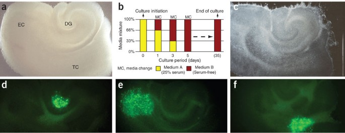
(a) Characteristic appearance in phase contrast of a hippocampal slice culture containing dentate gyrus (DG), entorhinal cortex (EC) and associated temporal cortex (TC) at 1 day in culture (dic). (b) During the first culture days, serum-containing medium is replaced by a defined, serum-free solution that enables culture intervals of at least 35 days. (c) Cultured in interphase conditions, slices thin out significantly, but maintain a surprising level of structural integrity (35 dic). Stereotactic deposition of donor cells can be achieved onto any anatomic structure of the cultured tissue (examples demonstrate grafted cells (d) in the hilar region of the DG, (e) in the EC and (f) within the TC at 1 day after deposition). In part reproduced with permission from Scheffler et al.24.
-
vii
Use three slices per ice-cold membrane insert; transfer into preincubated six-well plates; incubate in interface conditions at 35 °C, 5% CO2 until terminating culture.
-
viii
On day 1 in culture (dic), replace A-media with 1 ml of warm (66% A-media/34% B-media) media mixture per well (see Fig. 2b for culture protocol).
-
ix
On 3 dic, remove 80% of the media from each well and gently wash the slices in the culture inserts with 0.4 ml of warm (34% A-media/66% B-media) media mixture. Add 0.8 ml of warm (34% A-media/66% B-media) media into each well.
-
x
On 5 dic, remove 80% of the media from each well and gently wash the slices in the culture inserts with 0.4 ml of warm B-media. Add 0.8 ml of warm B-media into each well.
-
xi
Change B-media according to Step (x) every other day thereafter. At least 75% of the slices should maintain structural integrity for up to 35 dic (Fig. 2c).
-
xii
On 6–9 dic, prepare the setup for in vitro transplantation. Connect pulled glass pipette with tubing. Using disposable 1 ml syringes, flush the injection system (Hamilton syringe, attached tubing and glass pipette) with 70% EtOH and store the attached glass pipette in 70% EtOH for at least 1 h to disinfect equipment. Flush the injection system several times with DMEM/F12 to wash out any residual EtOH before aspirating the cell solution. Note that there should remain a 1–2 μl air cushion between the system fluid and the cell suspension to avoid potential cell damage and dilution during the transplantation procedure.
-
xiii
Remove one six-well plate from the incubator and wash the slices in the culture inserts with 0.4 ml of warm B-media. Immediately thereafter, deposit small volumes (i.e., <1 μl) of the cell solution onto the surface of each cultured slice using the manipulator of a sterotactic frame. Avoid touching the slice surface during this procedure.
-
xiv
Carefully return the culture plates to the incubator and monitor the location of transplanted cells regularly, beginning at day 1 after deposition (Fig. 2d–f).
-
xv
On the day after in vitro transplantation, thorough washing of the membrane inserts with warm B-media (in analogy to Step (x)) is advised. This procedure guarantees the removal of non-adherent/dead cells from the surfaces of cultured tissue. Continue according to Step (x) until the desired end point of the experiment.
-
xvi
Fix slices in ice-cold 4% paraformaldehyde (PFA) for at least 48 h to ensure highest tissue quality for subsequent histological studies. Note that 100% EtOH fixation yields superior tissue quality, but may result in enhanced autofluorescence that could interfere with the post hoc analysis of EGFP-expressing donor cells.
-
i
-
A

Specimen mounting and screening for transplanted neurons
Timing Approximately 5–15 min per slice
-
2
Transfer a tissue specimen into the recording chamber and fix it mechanically to the ground using the harp-like frame described in EQUIPMENT SETUP and switch on the perfusion.
Critical Step
Mechanical stress to the specimens should be avoided. The transfer of acutely prepared slices is best accomplished using a glass Pasteur pipette with a wide opening (brake off the pipette tip and put a rubber ball onto this end). Slice cultures from interphase conditions should be transferred on small pieces of the supporting membrane. To enable handling with a small forceps, carefully cut the membrane with a scalpel 1–2 mm around the cultured tissue.
-
3
In the bright field mode, focus with low magnification onto the surface of the slice, center the region of interest and switch to the water immersion objective. Apply a drop of bathing solution so that it runs down the objective and forms a fluid bridge between the front lens and the specimen. Adjust the DIC optics for good contrast.
-
4
Switch to epifluorescence and screen for transplanted cells. Once a cell of interest is located, adjust the gain of the camera while observing the intensity of fluorescence on the video monitor. Switch back and forth between epifluorescence and DIC modes to evaluate the quality of the cell soma. Stimulation of afferent fiber tracts and subsequent recording of evoked postsynaptic currents can be used to assess synaptic donor cell integration into particular networks. If you are doing this, use endogenous neurons as landmarks to place the stimtrode according to the projection and the position of the cell identified for recordings.
Critical Step
Avoid cell somata that look very crisp with sharply contrasted edges, swollen or blurry, and/or have a prominent swollen nucleolus. Neurons very close to the slice surface are usually injured by the slicing procedure and have to be avoided, too. Healthy neurons have a smooth surface and appear three-dimensional. Aim for solitary neurons to increase the probability of evaluating synaptic contacts between the recorded cell and host neurons.
Patch-clamp recording from identified neurons
-
5
Prepare a patch pipette and mount it onto the electrode holder. The filled patch pipette should not contain air bubbles. The filling should be just enough to have the tip of the chlorided silver wire dipping into the pipette solution. Tighten the cap of the holder and apply moderate positive pressure to the pipette via the tubing attached to the holder to avoid picking up dirt when the tip passes through the air–solution interface. Position the electrode's tip in the middle of the field of view, just above the solution of the chamber (low-magnification objective, e.g., ×5), then focus toward but slightly above the slice and move the electrode into the bath solution until the tip is focused.
-
6
Null the electrical offset of the electrode and apply a test pulse (e.g., 10 ms at 5 mV). Determine the current amplitude and calculate the pipette resistance applying the Ohm's law (a reasonable value is 3–5 MΩ; most patch-clamp software packages do the calculation automatically). Switch to the high-magnification objective, immerse the lens and focus onto the tip of the patch pipette. Lower the objective and the electrode successively until the tip is found just above the surface of the slice preparation.
Critical Step
The pipette resistance has to be adjusted to the size and membrane resistance (Rm) of the cells to be recorded and must be less than two orders of magnitude lower than Rm. For cells with very low Rm (<100 MΩ), one can use pipette solution containing certain blockers of ion channel different from the ones under investigation (e.g., Cs+, which blocks K+ channels).
-
7
Switch to epifluorescence, center the cell of interest and identify the cell of interest in the DIC mode. Close the shutter in the fluorescence light path. Approach the cell slowly with the patch pipette (continue to apply positive pressure) until noticing a slight dent on the cell's surface. Observe the current response to the test pulse on the oscilloscope or the computer monitor, and switch from positive pressure to applying gentle suction. The current response should level out (reading a pipette resistance in the gigaohms range). Only brief current peaks should be present at the beginning and the end of the test pulse. These transients arise from the loading of the electrode's capacitance.
Critical Step
The amount of pressure applied to the patch pipette has to be strong enough to prevent clogging of the tip while pushed through the tissue, yet gentle enough to avoid dislocation or breach of the cellular membrane to be recorded from. This balance will be found empirically.
-
8
Null the transients using the patch-clamp amplifier and set the holding potential to a value of −80 mV to hyperpolarize the cell after establishing the whole-cell configuration. This will avoid massive (and lethal) Ca2+ influx upon sudden depolarization when the cell is opened. While observing the current response to the test pulse on the oscilloscope or the computer monitor, apply gentle suction pulses of increasing strength until current transients appear. These transients arise from loading the cell's capacitance (Cm) and should be compensated using the controls of the patch-clamp amplifier. Now, the values of Cm, Rm and series resistance (Rs) should be determined.
Critical Step
Whereas Cm can serve as an indicator of cell size, Rs is an important measure for the quality of the voltage-clamp condition. For fast currents of high amplitude, Rs should be as low as possible. Electronic Rs compensation might be required. For spontaneous postsynaptic currents, demands are not that stringent (Rs<20 MΩ). However, time-consuming measurements require stable recording conditions; thus, Cm, Rm and Rs should be monitored periodically.
-
9
Recordings can be initiated as soon as a stable holding current and a leak as small as possible (<100 pA) are observed. Besides a stable and tight seal, the composition of the pipette solution critically determines the holding current. Thus, dialysis of the pipette and neuronal contents has to be complete. As diffusion rates depend on several parameters tens to hundreds of seconds have been reported31, one should wait for several minutes. Such a waiting period will also ensure the removal of residual pipette solution that has been released into the tissue while approaching the cell and—in case of K+—will depolarize the surrounding neurons. The above-described pipette solution permits current-clamp evaluation of passive membrane properties and firing patterns, which are important indicators of neuronal maturity. Common voltage step protocols enable the recording of whole-cell currents that can give some indication of the size of voltage-activated Na+ and K+ currents. Furthermore, this condition enables analysis of spontaneous synaptic input by recording membrane currents at holding potentials between −60 and −80 mV for several minutes. Owing to the relatively high Cl− content of the pipette solution, both glutamatergic and GABAergic inputs will yield negative-oriented postsynaptic currents at this holding potential (EGlu ≈ 0 mV, ECl ≈ –38 mV), which can be distinguished by their kinetics. Depending on the type of current to be recorded, the composition of the pipette solution should be adapted. For example, a solution with Cl− as the main anion works well for GABAA receptor-mediated currents, whereas for the detection of miniature excitatory postsynaptic currents (EPSCs), gluconate- or methylsulfonate-based solutions are frequently used.
Critical Step
Owing to the small amplitude of spontaneous EPSCs, it is important to keep noise as low as possible. A noise peak-to-peak amplitude of <20 pA is readily achieved by proper grounding and shielding. Additionally, keep an eye on the chlorided silver wires and pipette holders because deposits of salt and dirt or moisture in the holder increase noise. Further means of noise reduction (like coating of the pipette) can be found elsewhere16,17. Very low-amplitude signals should not be detected just by setting a detection threshold. Current analysis software (e.g., Clampex version 9) is able to distinguish meaningful signals from noise by comparing it to a kinetic template.
-
10
Switch to epifluorescence at the end of the recording process to take note of a potential “backflow” of fluorescence into the pipette tip (Fig. 3a,b). This observation should be documented as it serves as a strong indicator of the 'donor cell nature' of the recorded cell. Carefully handle shutter and filter wheel at this step to avoid breaking of the electrode tip.
Figure 3: Identification of recorded donor cells and afferent host fibers. 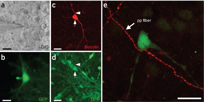
(a) Infrared DIC and (b) fluorescence image of an EGFP-expressing donor neuron during patch-clamp recording. The electrode approaches from the left. Backflow of donor cell EGFP into the recording electrode can serve as confirmation of donor cell identity. (c,d) Alternatively, biocytin fillings and post hoc immunohistochemistry can be used to identify recorded donor cells. Note the biocytin-filled donor cell in c (arrow) that is also positive for EGFP (d, arrow). The arrowhead depicts a dendritic process of the analyzed cell. (e) Anterograde labeling with rhodamine-conjugated dextran (Microruby) exposes vital afferent host fibers projecting toward EGFP-expressing donor neurons, thus enabling the functional analysis of host–donor synapses. In this example from hippocampal slice culture, afferent perforant path axons from the entorhinal cortex were found to contact tau-EGFP+ ES cell-derived donor neurons incorporated into the dentate gyrus granule cell layer. Scale bars, 20 μm. In part, reproduced with permission from Benninger et al.23.
Critical Step
The “backflow” of fluorescent indicator proteins will not always be observed; loss of fluorescence could provide alternative evidence instead. For additional post hoc analysis of recorded cells, fluorochrome-labeled avidin can be used to detect the neurobiotin (Fig. 3c,d) that was contained in the pipette solution. It is advised to try withdrawing the pipette very gently without destroying the cell after the recording.

Slice fixation for immunocytochemistry
-
11
After recording, use a small brush to transfer the tissue slice into a PBS-filled container for subsequent fixation in 4% PFA overnight at 4 °C.
Caution
Avoid any PFA contamination of the electrophysiology setup.
Troubleshooting
Vitality of slices and engrafted cells
With appropriate technique and practice, most slices will maintain their morphological (and functional) integrity for at least 35 days. Among the most frequent reasons for damage to the cultured tissue are lot variations of the B27 supplement (check with Invitrogen), a malfunctioning vibratome and trauma to the slice surface during the in vitro transplantation procedure. Good quality of slice cultures should ensure vitality of engrafted cells, unless cells were harmed during the preparation or transplantation procedures.
Troubleshooting advice can be found in Table 1.
Timing
Step 1A: 1 h
Step 1B: 30 min
Steps 2–4: 5–15 min
Steps 5–10: 15–45 min
Repeat Steps 5–10 for other appropriate donor neurons in the slice
Repeat Steps 2–10 for next slice
Anticipated results
There are a variety of highly sophisticated approaches that an experienced electrophysiologist could use for a sincere evaluation of integrated donor neuron function (outlined in the right column of Table 2). However, it is possible to reliably achieve a comprehensive characterization of functional integration (middle column of Table 2) applying commonly used techniques outlined in the main protocol presented here. These measures include information about vitality and performance of donor neurons, synaptic input, as well as synaptic donor–host interactions.
Pitfalls and current limitations:
A few obstacles complicate the technically simple procedure of recording functional data from labeled donor cells. The first stumbling block, inherent to every individual patch-clamp experiment, is to determine a representative cell for recordings. Marker gene expression and long-term identification of engrafted cells are influenced by (i) the choice of fluorochromes32,33,34,35, (ii) the specifics of construct and driving promoters36,37,38,39,40,41, as well as (iii) the transfection method employed and the resulting integration sites42,43,44,45. Single-cell RT-PCR analysis as well as post hoc immunohistochemistry could be used to exclude subpopulation analysis and to demonstrate additional features of recorded cells. A second issue relates to the conclusive identification of the recorded cell as donor cell-derived. Adequate documentation should include demonstration of EGFP outflow into the recording pipette (Fig. 3a,b), and/or post hoc labeling of neurobiotin with fluorochrome-conjugated avidin combined with a verification of marker gene expression (Fig. 3c,d). Lastly, cell fusion events need to be excluded to attribute recorded evidence of integration exclusively to the function of donor neurons. Appropriate techniques include the study of heterokaryon formation, FISH analysis, as well as Cre recombinase-based reporter systems where a constitutively active Cre recombinase and a Cre-inducible reporter gene are expressed in donor and host cells, respectively46,47,48,49. A challenging pitfall for the analysis of functional integration arises when engrafted donor cell populations show restricted migratory activity and accumulate around the transplantation site. In this case, cells can still be used to evaluate both, long-term survival and maturation of potentially self-sustaining donor cell networks. However, simple experimental strategies can be used to focus on individual host–donor cell interactions, too. These experiments would require selecting solitary donor cells for recordings that are located at the far-most end of the injection site, ideally within the reach of afferent host fibers. Incoming vital host projections can be visualized using anterograde tracer molecules (e.g., Microruby, Molecular Probes) enabling afferent fiber stimulation from remote distance for recording of elicited synaptic activity within the donor cell23 (Fig. 3e). Whereas these host–donor interactions are relatively easy to determine, the study of synaptic donor cell output into the host tissue remains a challenge. Depending on the vital marker used to identify the donor cells, it may be possible to follow EGFP-positive (donor cell) axons in three dimensions to determine putative recipient host cells. However, donor and recipient host cells are rarely ever found aligned in the 200- to 500-μm-thick acutely prepared brain sections commonly used for patch-clamp analysis. For these studies, alternative experimental platforms will have to be considered, for example, whole-mount preparations, long-term slice culture assays (Fig. 2) or in vivo patch-clamp analysis. Future analysis may also include the use of fluorophore-labeled species-specific presynaptic proteins to identify donor-formed synapses on host cells in xenograft paradigms, for example, employing the human-specific synaptophysin protein50.
Finally, the young field of reconstructive neurobiology must overcome a few classic challenges of neural cell transplantation. (i) A better understanding of local guiding cues and region-specific microenvironments is needed to facilitate controlled migration and integration of engrafted cells within the host parenchyma. (ii) New transplantation techniques are required to enable targeted, layer- or nucleus-specific introduction of solitary donor cells. (iii) A full grasp of the factors and protocols used to derive donor cells is required to generate “custom” neurons tailored to participate in the activities of specific local CNS networks51.
References
Wichterle, H., Lieberam, I., Porter, J.A. & Jessell, T.M. Directed differentiation of embryonic stem cells into motor neurons. Cell 110, 385–397 (2002).
Ahn, J.I. et al. Comprehensive transcriptome analysis of differentiation of embryonic stem cells into midbrain and hindbrain neurons. Dev. Biol. 265, 491–501 (2004).
Barberi, T. et al. Neural subtype specification of fertilization and nuclear transfer embryonic stem cells and application in parkinsonian mice. Nat. Biotechnol. 21, 1200–1207 (2003).
Watanabe, K. et al. Directed differentiation of telencephalic precursors from embryonic stem cells. Nat. Neurosci. 8, 288–296 (2005).
Andersson, E. et al. Identification of intrinsic determinants of midbrain dopamine neurons. Cell 124, 393–405 (2006).
Kawasaki, H. et al. Induction of midbrain dopaminergic neurons from ES cells by stromal cell-derived inducing activity. Neuron 28, 31–40 (2000).
Lee, S.H. et al. Efficient generation of midbrain and hindbrain neurons from mouse embryonic stem cells. Nat. Biotechnol. 18, 675–679 (2000).
Li, X.J. et al. Specification of motoneurons from human embryonic stem cells. Nat. Biotechnol. 23, 215–221 (2005).
Perrier, A.L. et al. Derivation of midbrain dopamine neurons from human embryonic stem cells. Proc. Natl. Acad. Sci. USA 101, 12543–12548 (2004).
Zeng, X. et al. Dopaminergic differentiation of human embryonic stem cells. Stem Cells 22, 925–940 (2004).
Scheffler, B., Edenhofer, F. & Brustle, O. Merging fields: stem cells in neurogenesis, transplantation, and disease modeling. Brain Pathol. 16, 155–168 (2006).
Goldman, S. Stem and progenitor cell-based therapy of the human central nervous system. Nat. Biotechnol. 23, 862–871 (2005).
Gorba, T. & Allsopp, T.E. Pharmacological potential of embryonic stem cells. Pharmacol. Res. 47, 269–278 (2003).
Lindvall, O., Kokaia, Z. & Martinez-Serrano, A. Stem cell therapy for human neurodegenerative disorders—how to make it work. Nat. Med. 10 (Suppl.): S42–S50 (2004).
Wobus, A.M. & Boheler, K.R. Embryonic stem cells: prospects for developmental biology and cell therapy. Physiol. Rev. 85, 635–678 (2005).
Walz, W., Boulton, A.A. & Baker, G.B. in Patch-Clamp Analysis. Advanced Techniques. 1st edn. (ed. Hoather-Potter, K.) 346 (Humana Press, Totowa, NJ, 2002).
Sakmann, B. & Neher, E. Single-channel Recording. 2nd edn. (Plenum Press, New York, 1995).
Hille, B. Ion Channels of Excitable Membranes. 3rd edn. 814 (Sinauer Associates, Sunderland, MA, 2001).
Brüstle, O., Maskos, U. & McKay, R.D.G. Host-guided migration allows targeted introduction of neurons into the embryonic brain. Neuron 15, 1275–1285 (1995).
Brüstle, O. et al. In vitro-generated neural precursors participate in mammalian brain development. Proc. Natl. Acad. Sci. USA 94, 14809–14814 (1997).
Wernig, M. et al. Functional integration of embryonic stem cell-derived neurons in vivo. J. Neurosci. 24, 5258–5268 (2004).
Brüstle, O. et al. Chimeric brains generated by intraventricular transplantation of fetal human brain cells into embryonic rats. Nat. Biotechnol. 16, 1040–1044 (1998).
Benninger, F. et al. Functional integration of embryonic stem cell-derived neurons in hippocampal slice cultures. J. Neurosci. 23, 7075–7083 (2003).
Scheffler, B. et al. Functional network integration of embryonic stem cell-derived astrocytes in hippocampal slice cultures. Development 130, 5533–5541 (2003).
Auerbach, J.M., Eiden, M.V. & McKay, R.D. Transplanted CNS stem cells form functional synapses in vivo. Eur. J. Neurosci. 12, 1696–1704 (2000).
Englund, U. et al. Grafted neural stem cells develop into functional pyramidal neurons and integrate into host cortical circuitry. Proc. Natl. Acad. Sci. USA 99, 17089–17094 (2002).
Schmandt, T. et al. High-purity lineage selection of embryonic stem cell-derived neurons. Stem Cells Dev. 14, 55–64 (2005).
Wernig, M. et al. Tau EGFP embryonic stem cells: an efficient tool for neuronal lineage selection and transplantation. J. Neurosci. Res. 69, 918–924 (2002).
Koch, P. et al. Transduction of human embryonic stem cells by ecotropic retroviral vectors. Nucleic Acids Res. 34, e120 (2006).
Cesnulevicius, K. et al. Nucleofection is the most efficient nonviral transfection method for neuronal stem cells derived from ventral mesencephali with no changes in cell composition or dopaminergic fate. Stem Cells 24, 2776–2791 (2006).
Pusch, M. & Neher, E. Rates of diffusional exchange between small cells and a measuring patch pipette. Pflugers. Arch. 411, 204–211 (1988).
Hadjantonakis, A.K. & Nagy, A. The color of mice: in the light of GFP-variant reporters. Histochem. Cell Biol. 115, 49–58 (2001).
Duden, R. Live cell imaging: the “green revolution” continues apace. Trends Cell Biol. 12, 548 (2002).
van Roessel, P. & Brand, A.H. Imaging into the future: visualizing gene expression and protein interactions with fluorescent proteins. Nat. Cell Biol. 4, E15–E20 (2002).
Miyawaki, A., Sawano, A. & Kogure, T. Lighting up cells: labelling proteins with fluorophores. Nat. Cell Biol. (Suppl.): S1–S7 (2003).
Young, P. & Feng, G. Labeling neurons in vivo for morphological and functional studies. Curr. Opin. Neurobiol. 14, 642–646 (2004).
Thomas, N. Fluorescent proteins and engineered cell lines. Methods Mol. Biol. 356, 165–187 (2007).
van den Pol, A.N. & Ghosh, P.K. Selective neuronal expression of green fluorescent protein with cytomegalovirus promoter reveals entire neuronal arbor in transgenic mice. J. Neurosci. 18, 10640–10651 (1998).
Chung, S. et al. Analysis of different promoter systems for efficient transgene expression in mouse embryonic stem cell lines. Stem Cells 20, 139–145 (2002).
Chung, S. & Kim, K.S. Transfection and promoter analysis in embryonic stem cells. Methods Mol. Biol. 329, 187–193 (2006).
Zeng, X. et al. Stable expression of hrGFP by mouse embryonic stem cells: promoter activity in the undifferentiated state and during dopaminergic neural differentiation. Stem Cells 21, 647–653 (2003).
Siemen, H. et al. Nucleofection of human embryonic stem cells. Stem Cells Dev. 14, 378–383 (2005).
Wallace, H., Ansell, R., Clark, J. & McWhir, J. Pre-selection of integration sites imparts repeatable transgene expression. Nucleic Acids Res. 28, 1455–1464 (2000).
Lakshmipathy, U. et al. Efficient transfection of embryonic and adult stem cells. Stem Cells 22, 531–543 (2004).
Miyoshi, G. & Fishell, G. Directing neuron-specific transgene expression in the mouse CNS. Curr. Opin. Neurobiol. 16, 577–584 (2006).
Terada, N. et al. Bone marrow cells adopt the phenotype of other cells by spontaneous cell fusion. Nature 416, 542–545 (2002).
Ying, Q.L., Nichols, J., Evans, E.P. & Smith, A.G. Changing potency by spontaneous fusion. Nature 416, 545–548 (2002).
Alvarez-Dolado, M. et al. Fusion of bone-marrow-derived cells with Purkinje neurons, cardiomyocytes and hepatocytes. Nature 425, 968–973 (2003).
Chen, K.A. et al. Fusion of neural stem cells in culture. Exp. Neurol. 198, 129–135 (2006).
Yan, J. et al. Extensive neuronal differentiation of human neural stem cell grafts in adult rat spinal cord. PLoS Med. 4, e39 (2007).
Goetz, A.K. et al. Temporally restricted substrate interactions direct fate and specification of neural precursors derived from embryonic stem cells. Proc. Natl. Acad. Sci. USA 103, 11063–11068 (2006).
Doyle, M.W. et al. Strategies for cellular identification in nucleus tractus solitarius slices. J. Neurosci. Methods 137, 37–48 (2004).
Brüstle, O. Building brains: neural chimeras in the study of nervous system development and repair. Brain Pathol. 9, 527–545 (1999).
Brüstle, O., Cunningham, M., Tabar, V. & Studer, L. Experimental transplantation in the embryonic, neonatal, and adult mammalian brain. in Current Protocols in Neuroscience. 8th edn. (eds. Crawley, J. et al.) 3.10.11–13.10.28 (Wiley, New York, 1997).
Acknowledgements
This work was supported by the Deutsche Forschungsgemeinschaft (SFB TR-3; Br 1337/3-2), the European Union (LSHG-CT-2006-018739; ESTOOLS) and the Hertie Foundation. B.S. was supported by NIH/NINDS Grant NS46384 and the Evelyn F. and William L. McKnight Brain Research Foundation. B.S. is involved with a biotechnology startup company, RegenMed Inc. This company is involved with stem cell technology related to human therapeutics.
Author information
Authors and Affiliations
Corresponding author
Ethics declarations
Competing interests
The authors declare no competing financial interests.
Rights and permissions
About this article
Cite this article
Opitz, T., Scheffler, B., Steinfarz, B. et al. Electrophysiological evaluation of engrafted stem cell-derived neurons. Nat Protoc 2, 1603–1613 (2007). https://doi.org/10.1038/nprot.2007.230
Published:
Issue Date:
DOI: https://doi.org/10.1038/nprot.2007.230
This article is cited by
-
Auto-attraction of neural precursors and their neuronal progeny impairs neuronal migration
Nature Neuroscience (2014)
Comments
By submitting a comment you agree to abide by our Terms and Community Guidelines. If you find something abusive or that does not comply with our terms or guidelines please flag it as inappropriate.
