

Performing Esophageal Manometry
This section describes the procedure for performing esophageal manometry using a minimally perfused pneumohydrolic system with computerized recording. The text summarizes the techniques for standard esophageal manometry and manometry of the upper esophageal sphincter (UES). A video demonstrates the esophageal manometric technique.
- Before bringing the patient into the room, (a) perform the motility setup checklist according to policy as described in the equipment's setup protocol, and (b) make sure the patient did not eat or drink anything for 3 to 6 hours prior to test.
- Bring the patient into the room and place gown over the upper body. The patient should lie on the bed (supine position).
- Select the catheter to be used:
- For esophageal manometry use a standard esophageal manometric tube; eight-lumen, 3-cm spaced catheter with Dent sleeve [perfusion port (P) 2].
- For UES manometry, use a standard upper esophageal manometric tube: eight-lumen with modified UES sleeve attached to the proximal end of the recording tube with sleeve (P6).
- Connect the manometric recording catheter to the perfusion pump (P1 on the tube to port 1 on the pump, P2 on the tube to 2 on the pump, and so on). Note: do not perfuse channels that are not being used for test.
- When the catheter is connected, perfuse the catheter via the pump.
- As the catheter is filled, and while the pump is still on, hold the recording tube at the level of the midaxillary region of the patient and adjust the baseline. This process varies depending on whether a computerized system or a chart recorder is used.
- This completes the process of calibration and set up.
- Proceed to test the patient.
Performing theProcedure using an Eight-lumen Catheter that Incorporates a Sleeve Device at Port 2
- Check that the patient is not allergic to Xylocaine. If he/she is, use a sterile lubricant.
- Numb nostril with 2% Xylocaine gel using 6-inch cotton tip applicator. (Use a sterile lubricant if patient is allergic to Xylocaine.
- Apply pneumo belt for monitoring respiration around the patient's lower chest of upper abdomen.
- Lubricate the manometric catheter with 2% Xylocaine (or sterile lubricant if the patient is allergic to Xylocaine) and insert through nasal passage.
- Place patient in the supine positio.
- Advance the catheter to the 60-cm mark. In taller individuals 65 cm may be required. With the catheter in this position, inspiration results in a pressure increase in those ports that are in the stomach and a pressure decrease in those that are in the esophagus.
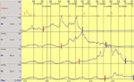
- Perform three breath-held (mid-expiration) rapid pull-throughs from approximately 60 cm to 40 cm (speed of withdrawal: 1 cm/s) of the lower esophageal sphincter to assess length and position of the sphincter. Figure 1 shows an example of lower esophageal sphincter (LES) rapid pull-through (1 cm/s). The distal margin of the LES high-pressure zone is marked with a red line. The proximal margin of the LES high-pressure zone is marked with a blue line. In this example the length of LES high-pressure zone averages 4 cm. Note that during this pull-through breathing is withheld at mid-expiration. Reinsert the catheter to the 60-cm (65-cm) mark between each pull-through.Perform one station pull-through of the LES. For this, patients should not hold their breath but they should be instructed to limit their spontaneous swallowing as much as possible. In this technique the recording ports are withdrawn at 1-cm increments and maintained at each position for approximately 15 to 20 seconds (two to three respirations). In Figure 2 the lower margin of the LES high-pressure zone is marked with a red line, whereas its upper margin is marked with a blue line.
Figure 1: Example of lower esophageal sphincter (LES) rapid pull-through technique (1 cm/s).
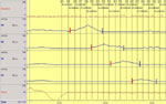
The distal margin of the LES high-pressure zone is marked with a red line. The proximal margin of the LES high-pressure zone is marked with a blue line. The length of the LES high-pressure zone averages 4 cm. Note that during this pull-through breathing is withheld at mid-expiration.
Figure 2: Example of station pull-through technique.
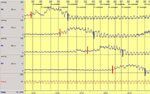
In this technique the recording ports are withdrawn at 1-cm increments and maintained at each position for approximately 15 to 20 s (two to three respirations). The distal margin of the LES high-pressure zone is marked with a red line, whereas its proximal margin is marked with a blue line.
- Position the sleeve within the sphincter such that the recording site at the proximal end of the sleeve (P3) records esophageal pressure as well as negative pressure upon deep inspiration, and the recording site distal to the sleeve (P1) is in the gastric region and a positive pressure is demonstrated upon deep inspiration (Figure 3).
Figure 3: Example of sleeve device properly positioned within the LES.
With the sleeve within the sphincter, the recording site at the proximal end of the sleeve (P3) records esophageal pressure as well as negative pressure upon deep inspiration. The recording site distal to the sleeve (P1) is in the gastric region and a positive pressure is demonstrated upon deep inspiration.
- Instruct patients to limit their spontaneous swallow, and then monitor the LES pressure for 5 minutes, instructing patients to obtain the resting LES pressure. Figure 4 shows an example of resting LES pressure recorded by a sleeve device. Each inspiration (dashed line) results in a decrease in intraesophageal pressures (P3–8) while it induces an increase in LES (sleeve–P2) and intragastric pressure (P1). Respiration is recorded with a pneumobelt (Resp). Each inspiration is seen as an upward deflection, whereas expiration is a downward deflection.
Figure 4: Example of the influence of respiration on esophageal, LES, and gastric pressures.
Each inspiration (dashed line) results in a decrease in intraesophageal pressure (P3-8) while inducing an increase in LES (sleeve–P2) and intragastric pressure (P1). Respiration is recorded with a pneumobelt (Resp). Each inspiration is seen as an upward deflection while expiration is a downward deflection.
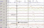
- Have the patient perform ten 5-mL water swallows to evaluate peristalsis and LES relaxation. Figure 5 shows examples of esophageal peristalsis and LES relaxation during three swallows of 5 mL water.
Figure 5: Examples of esophageal peristalsis and LES relaxation during three swallows each of 5 mL of water.

As seen, each water swallow (SW) results in the development of a peristaltic pressure wave that propagated distally (dark line). This is accompanied by relaxation of the LES.
- Evaluate the upper sphincter length by doing a pull-through of that region before removing the manometric catheter. A UES pull-through is used to locate the proximal and distal margins of the UES high pressure zone. In the example in Figure 6, the distal margin is marked with a red line, whereas the proximal margin is marked with a blue line.
Figure 6: Example of a UES pull-through.
It is used to locate the proximal and distal margins of the UES high-pressure zone. In this example the distal margin is marked with a red line, whereas the proximal margin is marked with a blue line.
- Evaluate peristalsis in the most proximal segment of the esophagus. Because the standard manometric catheter does not cover the most proximal segment of the esophagus, evaluation of peristalsis in this area is achieved by placing one of the manometric ports within the UES high-pressure zone (Figure 7). In this example, P6 (green line) is the port within the UES high-pressure zone. In this position, recording sites located distally will record pressure within the striated muscle region of the esophagus during swallows.
Figure 7: Example of proximal esophageal manometry.
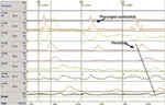
Because the standard manometric catheter does not cover the most proximal segment of the esophagus, evaluation of peristalsis in this area is achieved by placing one of the manometric ports within the UES high pressure zone (in this example P6–green line). In this position, recording sites located distally will record pressure within the striated muscle region of the esophagus during swallows.
- Place tube in the exact position of pretest zeroing while perfusing to check the baseline.
- Turn the perfusion off, and extubate.
Upper Esophageal Sphincter Manometry using a Sleeve Device (P6)
- Check that the patient is not allergic to Xylocaine. If he/she is, use a sterile lubricant.
- Numb nostril with Xylocaine gel using a 6-inch cotton applicator. (Use sterile lubricant if patient is allergic to Xylocaine.)
- Apply pneumo belt.
- Lubricate manometric catheter with Xylocaine (or sterile lubricant if the patient is allergic to Xylocaine) and insert through nasal passage.
- Place patient in supine position.
- Apply submental electromyography (EMG) swallow markers (two red leads under chin, black ground lead on arm).
- Advance catheter to the 30-cm mark.
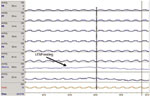
- Perform pull-through of the UES and position the sleeve in the UES such that the recording site proximal to the sleeve is recording from hypopharyngeal region and the recording site distal to the sleeve is recording esophageal pressure. This technique is similar to that of the lower esophageal sphincter (LES) pull-through in that the catheter is slowly withdrawn and the entry (red line) and exit (blue line) through the UES high pressure zone is monitored (Figure 8).
Figure 8: Example of pull-through technique for positioning the sleeve sensor within the UES.
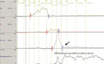
This technique is similar to that of the LES pull-through, in that the catheter is slowly withdrawn and the entry (red line) and exit (blue line) through the UES high-pressure zone are monitored. With the arrival of the manometric port located at the proximal margin of the UES sleeve device into the pharyngeal cavity (arrow), the sleeve sensor has just entered the UES high-pressure zone. At this time, the catheter is withdrawn another 2 cm, allowing the high-pressure zone to straddle the sleeve device in its middle section. In this position, the sleeve device will be able to continually record pressure during orad movement of the UES during swallowing.
- With the arrival of the manometric port located at the proximal margin of the UES sleeve device into the pharyngeal cavity (arrow), the sleeve sensor has just entered the UES high-pressure zone. At this time, the catheter is withdrawn another 2 cm, to allow the high-pressure zone to straddle the sleeve device in its middle section. In this position, the sleeve device will be able to continually record pressure during orad movement of the UES during swallowing.
- Obtain five dry swallows for evaluation of swallow-induced UES relaxation using the sleeve device (Figure 9). Owing to the orad movement of the UES during swallowing, pressure recordings using side-hole or isolated recording sites do not measure true swallow-induced UES relaxation. Use of a sleeve device that records the highest pressure along its entire length overcomes this problem. Examples of UES relaxation during two dry swallows are shown in Figure 9.
Figure 9: Examples of evaluation of swallow-induced UES relaxation using sleeve device.
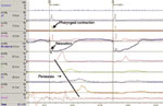
Owing to orad movement of the UES during swallowing, pressure recordings using a side-hole or isolated recording sites will not measure true swallow-induced UES relaxation. Use of a sleeve device that records the highest pressure along its entire length overcomes this problem. Examples of UES relaxation during two dry swallows are shown.
- Obtain five 5-mL water swallows.
- Place tube in exact position of pretest zeroing while perfusing to check the baseline.
- Turn perfusion off and extubate.
Video 1 demonstrates the manometric techniques described above.