
Abstract
The long-range spin-triplet supercurrent transport is an interesting phenomenon in the superconductor/ferromagnet ( ) heterostructure containing noncollinear magnetic domains. Here we study the long-range superharmonic Josephson current in asymmetric
  junctions. It is demonstrated that this current is induced by spin-triplet pairs
  −
−  or
or  +
+  in the thick
  layer. The magnetic rotation of the particularly thin
  layer will not only modulate the amplitude of the superharmonic current but also realise the conversion between
  −
−  and
and  +
+  . Moreover, the critical current shows an oscillatory dependence on thickness and exchange field in the
  layer. These effect can be used for engineering cryoelectronic devices manipulating the superharmonic current. In contrast, the critical current declines monotonically with increasing exchange field of the
  layer and if the
  layer is converted into half-metal, the long-range supercurrent is prohibited but
  still exists within the entire
  region. This phenomenon contradicts the conventional wisdom and indicates the occurrence of spin and charge separation in present junction, which could lead to useful spintronics devices.
Introduction
Superconductor/ferromagnet ( ) hybrid structure has recently attracted considerable attention because of the potential applications in spintronics and quantum information1,2,3 as well as the display of a variety of unusual physical phenomena4,5,6,7. In general, if a weak F is adjacent to an s-wave S and there is no interfacial spin-flip scattering, the normal Andreev reflection will generate at
  interfaces. The process involves an electron incident on the
  interface from the F at energies less than the superconducting energy gap. The incident electron forms a Cooper pair in the S with the retroreflection of a hole of opposite spin to the incident electron. Consequently, the conventional spin-singlet Cooper pair decays at a short range in ferromagnetic region. In
  Josephson junctions with homogeneous magnetization, through the normal Andreev reflection occurring at two
  interfaces, a Cooper pair is transferred from one S to another, creating a supercurrent flow across the junction8. As a consequence of the exchange splitting of the Fermi level of the F, the Cooper pair shows an oscillatory manner superimposed on an exponential decay in the F. Correspondingly, the Josephson current displays a damped oscillation with increasing the thickness or the exchange field of the F, leading to the appearance of the so-called “0-π transition”1,2. In general, the normal Andreev reflection will be suppressed by the exchange field of the F, so the Josephson current just can transport a short distance.
In contrast, if one insert a thin spin-active F layer with noncollinear magnetization into the  interface, it is found that the noncollinear magnetization can lead to a spin-flip scattering, then the reflected hole has the same spin as the incident electron, which is identified as anomalous Andreev reflection. When this reflection takes place at two
  interfaces, the parallel spin-triplet Cooper pairs
  are generated in the central F layer and can penetrate into F layer over a long distance unsuppressed by the exchange interaction, so that the proximity effect is enhanced. The induced long-range current manifests itself as a large first harmmonic (
 ) in the spectral decomposition of the Josephson current-phase relation
  8.
8.
It is worth to point that, if the central F layer is converted into fully spin-polarized half-metal, in which electronic bands exhibit insulating behavior for one spin direction and metallic behavior for the other, the normal Andreev reflection will be inhibited completely due to inability to form a pair in the S and impossibility of single-particle transmission. However, the strength of the anomalous Andreev reflection can not be strongly influenced by the spin-polarization of the F and the transport processes of  (or
(or  ) in the F region will continue to take place. In response, several different inhomogeneous configurations have been proposed for studying such enhanced proximity effect9,10,11,12,13,14,15. The corresponding experiments have proved these physical process and observed the strong enhancement of the long-range spin-triplet supercurrents16,17,18,19,20,21.
Different from the configurations mentioned above, it has proposed a long-range proximity effect develops in highly asymmetric  junction composed of thick
  layer and particularly thin
  layer with noncollinear magnetizations at low temperatures22,23,24. This effect arises from two normal Andreev reflections occurred at normal
  interface and two anomalous Andreev reflections at spin-active
  interface. The long-range spin-triplet correlations in this junction give the dominant second harmonic (
 ) in current-phase relation 23, which is known as superharmonic Josephson current22. Recently, Iovan et al.25 experimentally observed the long-range supercurrent through above junction. This second harmonic can be manifested as half-integer Shapiro steps that can be experimentally observed26 and the two times smaller flux quantum will be obtained, leading to more sensitive quantum interferometers (SQUIDs)27. It should be stressed that refs 22, 23, 24 did not discuss the difference of long-range triplet pairing fashion between asymmetric
  junction and symmetric
  . Moreover, it is high desirable to clarify the effect of the misorientation angle on the triplet pairing correlations in the
  junction, as well as the influence of the thickness and the exchange field in two ferromagnetic layers on the Josephson current and the long-range spin-triplet correlations.
In this work, we study the relation between the long-range superharmonic Josephson current and the spin-triplet pairing correlations in  junction. It is proposed that the superharmonic Josephson current is induced by the spin-triplet pairs
  −
−  or
or  +
+  in the long
  layer. The variation of the misorientation angle between two magnetizations will not only turn the amplitude of the superharmonic current but also realize the conversion between
  −
−  and
and  +
+  . This can be used to control the superharmic current and the pairing fashion in the
  layer through modulating the magnetic structure of the
  layer. Besides, the critical current shows an oscillatory dependence on the thickness and exchange field of the highly thin
  layer. These effect can be used for engineering cryoelectronic devices manipulating spin-polarized supercurrent. In contrast, the critical current decreases monotonically with increasing exchange field of the
  layer. Specifically, if the
  layer is converted into half-metal, the long-range Josephson current will be completely prohibited, but
  still exist in
  region. This phenomenon indicates the occurrence of spin and charge separation in present
  junction which could lead to useful spintronics devices. These results also contradict the traditional view: the long-range Josephson current is determined by the parallel spin-triplet pairs in the multilayer junction with noncollinear magnetization alignment between ferromagnetic layers. At last, it is also found that the magnetization of the
  layer will bring about a same direction magnetization in the
  layer on condition that the magnetic moment of the
  layer is weak.
To be more precise, we consider the Josephson junction consists of two s-wave superconducting electrodes and ferromagnetic bilayer with noncollinear magnetizations. The schematic picture of the  device is presented in Fig. 1. One assume that the transport direction is along the y axis and the system satisfies translational invariance in the x-z plane. The thicknesses of
  layer and
  layer are
  and
and  , respectively. The exchange field
  due to the ferromagnetic magnetizations in the
 layer is described by
  . Here
  is the tilt angle from the z axis and
  is the horizontal angle respect to x axis.

Schematic illustration of the S/F1/F2/S Josephson junction containing a bilayer ferromagnet.
Thick arrows in F1 layer and F2 layer indicate the directions of the magnetic moments. The phase difference between the two s-wave Ss is  .
.
Results
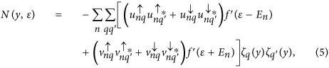
Based on the extended the Blonder-Tinkham-Klapwijk (BTK) approach28,29,30,31, the dc Josephson current in the  junction can be expressed as follows

where  are the Matsubara frequencies with
  and
and  .
.  are the perpendicular components of the wave vectors for electron-like (hole-like) quasiparticles in superconducting regions and
  with
with  are the scattering coefficients of the normal Andreev reflection under the condition of four different incoming quasiparticles, electron-like quasiparticles (ELQs) and hole-like quasiparticles (HLQs) with spin up and spin down. Then the critical current is derived from
  .
.
By applying the Bogoliubov’s self-consistent field method32,33, the triplet pair amplitudes are defined as follows34:


where  and equal-spin pair amplitude will be denoted by
  . The singlet pair amplitude writes as
  . In this paper, the singlet and triplet pair amplitudes are all normalized to the value of the singlet pairing amplitude in a bulk superconducting material. The LDOS is given by34
where  is the derivative of the Fermi function. The LDOS is normalized to unity in the normal state of the S material. In addition, the local magnetic moment in the
  geometry has three components34.


where  and
and  are the Bohr magneton and the Fermi function, respectively. It is convenient to normalize these components to
  .
.
Unless otherwise stated, in BTK approach we use the superconducting gap  as the unit of energy. The Fermi energy is
  , the interface transparency is
  and
and  . We measure all lengths and the exchange field strengths in units of the inverse of the Fermi wave vector
  and the Fermi energy
  , respectively. The magnetization in the
  layer is fixed along the z direction (
 ,
,  ), while the
  is a free layer in which the magnetization points any direction. In Bogoliubov’s self-consistent field method, we consider the low-temperature limit and take
  ,
,  . The other parameters are the same as the ones mentioned before.
Discussion
Superharmonic currents versus misalignment angle
From Fig. 2 one can clearly see that the critical current reaches maximum for perpendicular magnetizations ( ) and decreases to minimum as the magnetizations are parallel (
 ) or antiparallel (
 ) to each other. However, the variation of the angle
  can not lead to the change of critical current while keeping
  constant. It is known that characteristic variations of the critical current
  with the misaligned angles (
 ,
,  ) are related to the nature of pairing correlations. Figure 3 shows the spatial distribution of the spin-triplet pair amplitudes for different misalignment angle
  at fixed
  . It is found that the real part of
  and
and  can not penetrate entire
  layer, but their image parts can be distributed throughout this region. With increasing
  , the left parts of
  are almost unchanged, however, their right parts gradually decrease. Correspondingly, the amplitudes of
  increase and turn to maximum at
  . The main reason is because the x-projection of misaligned magnetic moment in the
  layer can generate two separate effects: spin-mixing and spin-flip scattering process9. The former will result a mixture of singlet pairs and triplet pairs with zero spin projection
  −
−  +
+  , where
  ,
,  is the Fermi velocity and R is the distance from the
  interface. The latter can convert
 into the parallel spin-triplet pairs
 3. These parallel spin pairs will penetrate coherently over a long distance into the
  layer. So the transport of
 can make a significant contribution to superharmonic Josephson current. Meanwhile, the period of this current becomes π and satisfies the second harmonic current-phase relation
  22,24. By contrast, in the Josephson junction with ferromagnetic trilayer only spin-triplet pairs
  (or
(or  can transmit in central ferromagnetic layer, which provide the main contribution to the long-range first harmonic current35.

Critical current as a function of the orientation angle (θ2, φ2) of the F2 layer.
Here we set  ,
,  ,
,  and
and  .
.

The spin-triplet pair amplitudes f0 and f1 plotted as a function of the coordinate kFy for several values of θ2 in the case of φ2 = 0.
The left panels show the real parts while the right ones show the imaginary parts. The dotted vertical lines represent the location of the  ,
,  and
and  interfaces. Here
  ,
,  ,
,  ,
,  ,
,  and
and  . All panels utilize the same legend.
As plotted in Fig. 4, in the case of collinear orientation of magnetizations ( ), the current
  is weak enough and present a first harmonic feature. At this time, the long-range spin-triplet pairs
 are absent, so the LDOS in the
  layer is almost equal to its normal metal value. With increasing
  , the magnitude of the second harmonic current is enhanced by the increased number of
 . Specifically, for orthogonal magnetizations (
 ), the second harmonic current grows big enough. Correspondingly, the LDOS is significantly enhanced with two distinguishable peaks. Moreover, the spatial profile of the local magnetic moments are plotted for several values of
  in Fig. 5. What’s most interesting is that the component
  grows very quickly in the
  region with increasing
  and also displays the penetration of the same component into the
  region. The induced
  in the
  region does not only change magnitude as a function of position, but it also rotates direction. However, the component
  in the
  region will gradually decrease with
  and remains almost unchanged in the
  region.

(a) the Josephson current-phase relation Ie(ϕ) for four values of the relative angle θ2 between magnetizations. (b) The normalized LDOS in the F1 layer ( ) plotted versus the dimensionless energy
  for different θ2 and the results are calculated at
  . Other parameters are the same as in Fig. 3.

The x (top panels) and z components (bottom panels) of the local magnetic moment plotted as a function of the coordinate kFy for different θ2.
The left panels show the behaviours over the extended F1 regions while the right ones show the detailed behaviours in the F2 layer. Other parameters are the same as in Fig. 3.
As stated above, the variation of the horizontal angle  can not influence the Josephson current as the tilt angle
  has a fixed value. However, the change of
  will induced a conversion of pairing fashion in the
  region. As shown in Fig. 6, on the condition of
  ,
,  decrease gradually from a finite value to zero with increasing
  , but
, but  exhibit the opposite characteristics. These phenomena can be explained as follows: since the magnetic direction of the
  layer is oriented along the x axis (
 ,
,  ),
),  +
+  in the
  layer can be converted into
 in the
  layer. In contrast, if the magnetic moment of the
  layer is along y axis (
 ,
,  ),
),  +
+  will be transformed into
  +
+  , which can also penetrate into the
  region a long distance and make a major contribution to the second harmonic current. At the same time, when the magnetization direction of the
  layer rotates from the x axis to the y axis, the induced magnetic moment in the
  layer would correspondingly turn from
  to
to  , as seen in Fig. 7. In what follows, we focus on the dependence of the critical current on the thickness and exchange fields of two ferromagnetic layers under the condition of
  .
.

The spin-triplet pair amplitudes f1 [(a,b)] and f2 [(c,d)] plotted as a function of the coordinate  for several values of
  in the case of
  . The left panels [(a,c)] show the real parts while the right ones [(b,d)] show the imaginary parts. Other parameters are the same as in Fig. 3.

The x (top panels) and y components (bottom panels) of the local magnetic moment plotted as a function of the coordinate kFy for different φ2.
The left panels show the behaviours over the extended F1 region while the right ones show the detailed behaviours in the F2 region. Other parameters are the same as in Fig. 3.
Superharmonic currents versus thickness and exchange field of the spin-active  layer
layer
 layer
layerFigure 8 shows the dependence of the critical current Ic on the length  and exchange field
  for different misalignment angle
  when the
  layer has fixed values
  and
and  . One can see that Ic is sufficiently weak and decays in an oscillatory manner in parallel (
 ) and antiparallel (
 ) alignments of the magnetizations. This is because the exchange field in the F2 layer induces a splitting of the energy bands for spin up and spin down. This effect can make
  oscillate with a period
  and simultaneously decay exponentially on the length scale of
  1. Here,
  is the magnetic coherence length. In this case, only the spin-singlet pairs
  −
−  and spin-triplet pairs
  +
+  exist in the ferromagnetic layer. These two types of pairs can be suppressed by the exchange field of ferromagnetic layer and mainly provide the contribution to the first harmonic current.

Critical current (a) as a function of  and θ2 for
  and (b) as a function of
  and θ2 for
  . We set
  ,
,  and
and  .
.
On the other hand, if the orientations of the magnetic moments are perpendicular to each other ( ), Ic also displays the oscillated behaviour with increasing
  , but its order of magnitude is larger than for collinear magnetizations. This characteristic behaviour can be attributed to the spatial oscillations of
  +
+  in the F2 region with period Q · R. It is well known that the Cooper pair in the F2 layer will acquire a total momentum Q because of the spin splitting of the energy bands. As described in ref. 36, for a fixed Q the amplitude of
  +
+  will vary with the length R (=kFL2) of the F2 layer. As a result, the oscillated
  +
+  can be converted into
  −
−  in the F1 layer by the spin-flip scattering and then
  −
−  can propagate over long distance in the F1 layer and lead to the enhanced superharmonic current. Similarly, if one fixes
  and changes
  , the same features about the critical current can be obtained (see Fig. 8(b)). It is worth mentioning that this oscillatory behaviour could be different from the oscillation of the critical current with the thickness of F2 layer in
  junction36, because the supercurrent in the central F1 layer derives from the contribution of
  and manifests itself as a dominant first harmonic in the Josephson current-phase relation.
Superharmonic currents versus length and exchange field of the long F1 layers
In Fig. 9 the dependence of the critical current Ic on exchange field  and length
  are plotted for
  . Compared with the Josephson junctions with homogeneous magnetization, Ic in this asymmetric junctions decreases slowly with increasing
  on the weak or moderate exchange fields. This feature illustrates that
  −
−  will propagate coherently over long distances in the F1 layer. Furthermore, Ic are almost monotonically decreasing with
  for various
  and will be prohibited completely at
  . It indicates that the superharmonic current will be suppressed by the exchange field of the F1 layer. This phenomenon is clearly different from the first harmonic current in the half-metal Josephson junction with interface spin-flip scattering9,16, because the first harmonic current induced by
  can not be suppressed by the exchange splitting.

Critical current as a function of  and
and  We set
  ,
,  ,
,  and
and  .
.
In order to clearly explain the contribution of the spin-triplet pairs to the superharmonic current, we choose a fixed length  for discussion, as illustrated by the red line in Fig. 9. Under such conditions, we plot the distribution of the spin-triplet pairing functions f0, f1,
  and
and  for three exchange fields
  , 0.5 and 1.0 in Fig. 10. With increasing
  , the magnitude of f0 and f1 in the F1 region are all reduced and f0 drops to zero at
  . The reason can be summarized as follows: for weak exchange field
  the triplet correlations
  and
and  will generate in the F2 region and then combine into f1 in the F1 region. f1 decay spatially with approaching the
  interface due to the fact that the pairs
  and
and  are recombined into the pairs
  and
and  by the normal Andreev reflections. For
  ,
,  and
and  near the
  interface are both restrained. By contrast,
  adjacent to the
  interface increases instead. Moreover, because
  on the left side of F1 layer is suppressed, the recombination effect at the
  interface becomes weakened, in which case the superharmonic current will decrease. For a fully spin-polarized half-metal (
 ), Fig. 10(d) shows that
  will be completely suppressed, but
  does not vanish and it’s magnitude seems to be a slight increase in the vicinity of the
  interface (see Fig. 10(c)). These characters can be attributed to the contributions from two important phenomena taking place at the
  interface: normal Andreev reflections and normal reflections, as shown in Fig. 11 (a,b), respectively.

The imaginary parts of f0 (a), f1 (b),  (c) and
  (d) plotted as a function of the coordinate
  for several
  . We set
  ,
,  ,
,  ,
,  ,
,  ,
,  and
and  .
.

Two types of transference about the pairs of correlated electrons and holes.
(a) The first one consists of two normal Andreev reflections occurred at  interface and two anomalous Andreev reflections at
  interface in the case of weak exchange field in the F1 layer. (b) The second one consists of two normal reflections at
  interface and two anomalous Andreev reflections at
  interface while the F1 layer is converted into half-metal.
If the exchange field  is weak enough, the normal Andreev reflections will mainly occur at the
  interface, which provide the main contribution to Ic. In this case, the number of the pairs
  approximately equal to
  and then
  and
and  can combine into
 . Subsequently,
  −
−  can be converted into
  −
−  in the left S. With increasing
  , the normal Andreev reflections are gradually being replaced by the normal reflections and the difference in the number of
  and
and  will enlarge simultaneously. As a result, the transition from
  −
−  to
to  −
−  occurred at the
  interface will be weakened. In the fully spin-polarized case (
 ) the absence of the spin down electrons makes it impossible to generate the normal Andreev reflections at
  interface and therefore the Josephson current is completely suppressed but
  still exist. As depicted in Fig. 11(b), the electron transfer process is analogous to the unconventional equal-spin Andreev-reflection process reported in Ref. 37. Look at the whole picture, it is easy to understand the above process:
  injecting from the right S is converted into
  in the F1 layer and
  will be consequently reflected normally back as
  at the
  interface. Then
  is transformed into
  by the spin-flip scattering of the F2 layer. At last,
  transports to the right S. In the whole process, none of Coopers can penetrate into the left S, so the Josephson current would be suppressed completely.
In order to facilitate the experimental observations for the future, we plot the current-phase relation and the LDOS in the F1 layer at three points  , 0.5 and 1.0 in Fig. 12. With increasing
  , the superharmonic current
  decreases and two distinguishable peaks in the LDOS will become weak correspondingly. It’s particularly noteworthy that if
  Josephson current was completely suppressed but the LDOS displays a sharp zero energy conductance peak which marks the presence of
  . It can be measured in principle by STM experiments. And this feature is different from the conventional views: (i) The long-range triplet Josephson current is proportional to the parallel spin-triplet pairs
  or
or  . (ii) If the long-range triplet supercurrent passes through the Josephson junction, there will present the zero energy conductance peak in the LDOS of F. Finally, we discuss the influence of
  on the local magnetic moment. As can be seen from Fig. 13, in the F1 region Mz will grow with the increase of
  , but the induced Mx could be suppressed. For
  , Mz reaches maximum but Mx will disappear. By contrast, Mx in the F2 region hardly changes with
  and Mz will partly permeate into the F2 layer.

(a) the Josephson current-phase relation Ie(ϕ) for different  . (b) The normalized LDOS in the F1 layer (
 ) plotted versus the dimensionless energy
  and the results are calculated at
  . Other parameters are the same as in Fig. 10.

The x (top panels) and z components (bottom panels) of the local magnetic moment plotted as a function of the coordinate kFy for different h1/EF.
The left panels show the behaviours over the extended F1 region while the right ones show the detailed behaviours in the F2 layer. Other parameters are the same as in Fig. 10.
To summarize, we have studied the long-range superharmonic Josephson current and the spin-triplet pairing correlations in the asymmetric  junction. We have shown that the superharmonic current was induced by the spin-triplet pairs
  −
−  or
or  +
+  in the long F1 layer. The rotation of the magnetic moment in the thin spin-active F2 layer will not only modulate the amplitude of the superharmonic current through the junctions, but also realize the conversion from
  −
−  to
to  +
+  in the F1 layer. Besides, the critical current oscillates with the length and exchange field in the F2 layer. These features provide an efficient way to control the superharmonic current and the spin-triplet pairing fashion by changing the magnetic moment of the F2 layer. Specifically, the critical current almost decreases monotonically with the exchange field of the F1 layer and if the F1 layer is converted into half-metal, the Josephson current disappear completely but the spin-triplet pairs
  still exist within the entire F1 layer. This behavior is different from the conventional view about the relationship between the long-range current and the parallel spin-triplet pairs in the junctions with ferromagnetic trilayers. These results therefore indicated that the spin and charge degrees of the freedom can be separated in practice in the junction with ferromagnetic bilayers and suggested the promising potential of these junctions for spintronics applications.
Methods
The BCS mean-field effective Hamiltonian is given by1,32
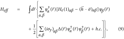
where  is the single-particle Hamiltonian,
  and
and  are creation and annihilation operators with spin α.
  and EF denote Pauli matrix and the Fermi energy, respectively.
  describes the superconducting pair potential with
  . Here
  accounts for the temperature-dependent energy gap. It satisfies the BCS relation
  , where
  is the energy gap at zero temperature and Tc is the superconducting critical temperature.
  is the unit step function and
  is the phase of the left (right) S.
By making use of the Bogoliubov transformation  and the anticommutation relations of the quasiparticle annihilation and creation operators
  and
and  , we have the Bogoliubov-de Gennes (BdG) equation1,32

Blonder-Tinkham-Klapwijk approach
The BdG equation (10) can be solved for each superconducting electrode and each F layer, respectively. For an incident spin up electron in the left S, the wave functions in the S leads and the Fp layer are


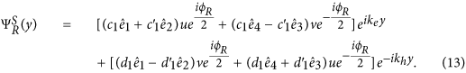
Here  ,
,  ,
,  ,
,  are basis wave functions. Quasiparticle amplitudes are defined as
  and
and  with
with  . The perpendicular components of the ELQs (HLQs) wave vector in S leads and Fp layer are given by
  and
and  with
with  , respectively. It is worthy to note that the parallel component
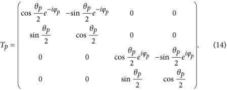
  is conserved in transport processes of the quasiparticles. The matrix can be defined as38
The coefficients  ,
,  ,
,  and a1 describe normal reflection, the normal reflection with spin-flip, anomalous Andreev reflection and normal Andreev reflection, respectively.
  (r = 1–8) are quasiparticles wave function amplitudes in the Fp layer. Likewise, c1, d1,
  and
and  are the quasiparticles transmission amplitudes in the right superconducting electrode. All scattering coefficients can be determined by solving the continuity conditions of the wave function and its derivative at the interface
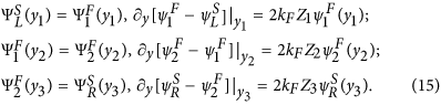
Here  are dimensionless parameters describing the magnitude of the interfacial resistances.
  are local coordinate values at the interfaces and
  is the Fermi wave vector. From the boundary conditions, we obtain a system of linear equations that yield the scattering coefficients.
Bogoliubov’s self-consistent field method
We put the  junction in a one-dimensional square potential well with infinitely high walls, then the eigenvalues and eigenvectors of the BdG equation (10) have the following changes:
  and
and  . Accordingly, the corresponding quasiparticle amplitudes can be expanded in terms of a set of basis vectors of the stationary states39,
  =
=  and
and  with
with  . Here, q is a positive integer and
  . LS1 and LS2 are the thicknesses of the left and right superconducting electrodes, respectively. The superconducting pair potential in the BdG equation (10) is determined by the self-consistency condition32

where the primed sum of En is over eigenstates corresponding to positive energies smaller than or equal to the Debye cutoff energy ωD and the superconducting coupling parameter g(y) is a constant in the superconducting regions and zero elsewhere. Iterations are performed until self-consistency is reached, starting from the stepwise approximation for the pair potential.
Additional Information
How to cite this article: Meng, H. et al. Long-range superharmonic Josephson current and spin-triplet pairing correlations in a junction with ferromagnetic bilayers. Sci. Rep. 6, 21308; doi: 10.1038/srep21308 (2016).
References
Buzdin, A. I. Proximity effects in superconductor-ferromagnet heterostructures. Rev. Mod. Phys. 77, 935 (2005).
Bergeret, F. S., Volkov, A. F. & Efetov, K. B. Odd triplet superconductivity and related phenomena in superconductor-ferromagnet structures. Rev. Mod. Phys. 77, 1321 (2005).
Eschrig, M. Spin-polarized supercurrents for spintronics. Phys. Today 64(1), 43 (2011).
Nussinov, Z., Shnirman, A., Arovas, D. P., Balatsky, A. V. & Zhu, J. X. Spin and spin-wave dynamics in Josephson junctions. Phys. Rev. B 71, 214520 (2005).
Sperstad, I. B., Linder, J. & Sudbø, A. Josephson current in diffusive multilayer superconductor/ferromagnet/superconductor junctions. Phys. Rev. B 78, 104509 (2008).
Colci, M., Sun, K., Shah, N., Vishveshwara, S. & Harlingen, D. J. V. Anomalous polarization-dependent transport in nanoscale double-barrier superconductor/ferromagnet/superconductor junctions. Phys. Rev. B 85, 180512(R) (2012).
Sun, K., Shah, N. & Vishveshwara, S. Transport in multiterminal superconductor/ferromagnet junctions having spin-dependent interfaces. Phys. Rev. B 87, 054509 (2013).
Golubov, A. A., Kupriyanov, M. Y. & Ilichev, E. The current-phase relation in Josephson junctions. Rev. Mod. Phys. 76, 411 (2004).
Eschrig, M., Kopu, J., Cuevas, J. C. & Schön G. Theory of Half-Metal/Superconductor Heterostructures. Phys. Rev. Lett. 90, 137003 (2003); Eschrig, M. & Lofwander, T. Triplet supercurrents in clean and disordered half-metallic ferromagnets. Nature Physics4, 138 (2008).
Bergeret, F. S., Volkov, A. F. & Efetov, K. B. Long-Range Proximity Effects in Superconductor-Ferromagnet Structures. Phys. Rev. Lett. 86, 4096 (2001).
Volkov, A. F., Bergeret, F. S. & Efetov, K. B. Odd Triplet Superconductivity in Superconductor-Ferromagnet Multilayered Structures. Phys. Rev. Lett. 90, 117006 (2003).
Asano, Y., Tanaka, Y. & Golubov, A. A. Josephson Effect due to Odd-Frequency Pairs in Diffusive Half Metals. Phys. Rev. Lett. 98, 107002 (2007); Asano, Y., Sawa, Y., Tanaka, Y. & Golubov, A. A. Odd-frequency pairs and Josephson current through a strong ferromagnet. Phys. Rev. B76, 224525 (2007).
Volkov, A. F. & Efetov, K. B. Odd spin-triplet superconductivity in a multilayered superconductor-ferromagnet Josephson junction. Phys. Rev. B 81, 144522 (2010).
Alidoust, M., Linder, J., Rashedi, G., Yokoyama, T. & Sudbø, A. Spin-polarized Josephson current in superconductor/ferromagnet/superconductor junctions with inhomogeneous magnetization, Phys. Rev. B 81, 014512 (2010).
Halasz, G. B., Blamire, M. G. & Robinson, J. W. A. Magnetic-coupling-dependent spin-triplet supercurrents in helimagnet/ferromagnet Josephson junctions. Phys. Rev. B 84, 024517 (2011).
Keizer, R. S. et al. A spin triplet supercurrent through the half-metallic ferromagnet CrO2 . Nature 439, 825 (2006).
Anwar, M. S., Czeschka, F., Hesselberth, M., Porcu, M. & Aarts, J. Long-range supercurrents through half-metallic ferromagnetic CrO2 . Phys. Rev. B 82, 100501(R) (2010).
Robinson, J. W. A., Witt, J. D. S. & Blamire, M. G. Controlled Injection of Spin-Triplet Supercurrents into a Strong Ferromagnet. Science 329, 59 (2010).
Khaire, T. S., Khasawneh, M. A., Pratt, W. P., Jr. & Birge, N. O. Observation of Spin-Triplet Superconductivity in Co-Based Josephson Junctions. Phys. Rev. Lett. 104, 137002 (2010).
Sprungmann, D., Westerholt, K., Zabel, H., Weides, M. & Kohlstedt, H. Evidence for triplet superconductivity in Josephson junctions with barriers of the ferromagnetic Heusler alloy Cu2MnAl. Phys. Rev. B 82, 060505(R) (2010).
Klose, C. et al. Optimization of Spin-Triplet Supercurrent in Ferromagnetic Josephson Junctions. Phys. Rev. Lett. 108, 127002 (2012).
Trifunovic, L. Long-Range Superharmonic Josephson Current. Phys. Rev. Lett. 107, 047001 (2011).
Trifunovic, L., Popovic′, Z. & Radovic′, Z. Josephson effect and spin-triplet pairing correlations in SF1F2S junctions. Phys. Rev. B 84, 064511 (2011).
Richard, C., Houzet, M. & Meyer, J. S. Superharmonic Long-Range Triplet Current in a Diffusive Josephson Junction. Phys. Rev. Lett. 110, 217004 (2013).
Iovan, A., Golod, T. & Krasnov, V. M. Controllable generation of a spin-triplet supercurrent in a Josephson spin valve. Phys. Rev. B 90, 134514 (2014).
Sellier, H., Baraduc, C., Lefloch, F. & Calemczuk, R. Half-Integer Shapiro Steps at the 0? π Crossover of a Ferromagnetic Josephson Junction. Phys. Rev. Lett. 92, 257005 (2004).
Radovic′, Z., Dobrosavljevic′-Grujic′, L. & Vujic′ic′, B. Coexistence of stable and metastable 0 and π states in Josephson junctions. Phys. Rev. B 63, 214512 (2001).
Blonder, G. E., Tinkham, M. & Klapwijk, T. M. Transition from metallic to tunneling regimes in superconducting microconstrictions: Excess current, charge imbalance and supercurrent conversion. Phys. Rev. B 25, 4515 (1982).
Furusaki, A. & Tsukada, M. Dc Josephson effect and Andreev reflection. Solid State Commun. 78, 299 (1991).
Zheng, Z. M. & Xing, D. Y. Josephson supercurrent with spin-equal pairing through a half-metallic link. J. Phys.: Condens. Matter 21, 385703 (2009).
Tanaka, Y. & Kashiwaya, S. Theory of Josephson effects in anisotropic superconductors. Phys. Rev. B 56, 892 (1997).
de Gennes, P. G. Superconductivity of Metals and Alloys. Chapt. 5 (Benjamin, New York, 1966).
Ketterson, J. B. & Song, S. N. Superconductivity, Part III (Cambridge University Press, 1999).
Halterman, K., Valls, O. T. & Barsic, P. H. Induced triplet pairing in clean s-wave superconductor/ferromagnet layered structures. Phys. Rev. B 77, 174511 (2008).
Houzet, M. & Buzdin, A. I. Long range triplet Josephson effect through a ferromagnetic trilayer. Phys. Rev. B 76, 060504(R) (2007).
Meng, H., Wu, X. Q. & Zheng, Z. M. Long-range triplet Josephson current modulated by the interface magnetization texture. Europhys. Lett. 104, 37003 (2013).
Visani, C. et al. Equal-spin Andreev reflection and long-range coherent transport in high-temperature superconductor/half-metallic ferromagnet junctions. Nature Physics 8, 539 (2012).
Jin, L. J., Wang, Y., Wen, L., Zha, G. Q. & Zhou, S. P. Spin-triplet current in half metal/conical helimagnet/superconductor heterojunctions. Phys. Lett. A 376, 2435 (2012).
Landau, L. D. & Lifshitz, E. M. Quantum Mechanics, Non-Relativistic Theory, third edition (Pergamon, Elmsford, NY, 1977).
Acknowledgements
This work is supported by the State Key Program for Basic Research of China under Grants No. 2011CB922103 and No. 2010CB923400, the National Natural Science Foundation of China under Grants No. 11174125, No. 11074109, No. 51106093 and No. 11447112, the Scientific Research Program Funded by Shaanxi Provincial Education Department Grant No. 12JK0972 and No. 15JK1132, the Scientific Research Foundation of Shaanxi University of Technology Grant No. SLG-KYQD2-01. J. Wu would like to thank the Shenzhen Peacock Plan and Shenzhen Fundamental Research Foundation Grant No. JCYJ20150630145302225.
Author information
Authors and Affiliations
Contributions
H.M. and J.S.W. conceived the research and performed the calculations. X.Q.W. and M.Y.R. gave scientific advice. H.M. wrote the main manuscript text and J.S.W. made an improvement. Y.J.R. prepared all the figures. All authors discussed and reviewed the manuscript.
Ethics declarations
Competing interests
The authors declare no competing financial interests.
Rights and permissions
This work is licensed under a Creative Commons Attribution 4.0 International License. The images or other third party material in this article are included in the article’s Creative Commons license, unless indicated otherwise in the credit line; if the material is not included under the Creative Commons license, users will need to obtain permission from the license holder to reproduce the material. To view a copy of this license, visit http://creativecommons.org/licenses/by/4.0/
About this article

Cite this article
Meng, H., Wu, J., Wu, X. et al. Long-range superharmonic Josephson current and spin-triplet pairing correlations in a junction with ferromagnetic bilayers. Sci Rep 6, 21308 (2016). https://doi.org/10.1038/srep21308
Received:
Accepted:
Published:
DOI: https://doi.org/10.1038/srep21308
This article is cited by
-
Inhomogeneous Spin Diffusion in Thickness-Controlled La 0 . 6 7 Sr 0 . 3 3 MnO 3 /YBa 2 Cu 3 O 7 − δ /La 0 . 6 7 Sr 0 . 3 3 MnO 3 Trilayers
Journal of Superconductivity and Novel Magnetism (2016)
Comments
By submitting a comment you agree to abide by our Terms and Community Guidelines. If you find something abusive or that does not comply with our terms or guidelines please flag it as inappropriate.
